
Storage System Hardware Owner's Manual
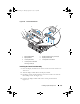
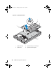
Table Of Contents
- Hardware Owner’s Manual
- About Your System
- Using the System Setup Program
- Installing System Components
- Recommended Tools
- Inside the System
- Front Bezel
- Opening and Closing the System
- Hard Drives
- Replacing a Hard-Drive Carrier
- Power Supplies
- System Fans
- Cooling Shroud
- Fan Brackets
- Cable Routing
- SAS Controller Daughter Card
- Configuring the Boot Device
- Expansion Cards
- Expansion-Card Cage
- DRAC Card and Cables
- Optical Drive and Cable
- System Memory
- Activating the Integrated NIC TOE
- Processors
- System Battery
- Expansion-Card Riser Boards
- Sideplane Board
- SAS Backplane Board
- Control Panel Assembly (Service-only Procedure)
- System Board (Service-only Procedure)
- Troubleshooting Your System
- Safety First-For You and Your System
- Start-Up Routine
- Checking the Equipment
- Troubleshooting Basic I/O Functions
- Troubleshooting a NIC
- Troubleshooting a Wet System
- Troubleshooting a Damaged System
- Troubleshooting the System Battery
- Troubleshooting Power Supplies
- Troubleshooting System Cooling Problems
- Troubleshooting System Memory
- Troubleshooting an Optical Drive
- Troubleshooting an External SCSI Tape Drive
- Troubleshooting a Hard Drive
- Troubleshooting a SAS Controller Daughter Card
- Troubleshooting Expansion Cards
- Troubleshooting the Microprocessors
- Running the System Diagnostics
- Jumpers and Connectors
- Getting Help
- Glossary
- Index

Installing System Components 125
NOTE: While removing the memory modules, record the memory module socket
locations to ensure proper installation.
10
Remove the heatsink(s) and microprocessor(s). See "Removing a
Processor" on page 105.
11
Remove the TOE key, if present. See Figure 6-2 for the location of the
TOE key.
12
Remove the sideplane. See "Removing the Sideplane Board" on page 116.
13
Remove the SAS backplane. See "Removing the SAS Backplane Board" on
page 118.
14
Remove the system board:
a
Pull the system-board tray riser release pin. See Figure 3-28.
b
While pulling the release pin, slide the system-board tray toward the
front of the chassis.
c
Lift up the system-board tray and remove it from the chassis.
Book.book Page 125 Monday, September 14, 2009 12:57 PM