
Storage System Hardware Owner's Manual
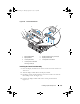
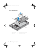
Table Of Contents
- Hardware Owner’s Manual
- About Your System
- Using the System Setup Program
- Installing System Components
- Recommended Tools
- Inside the System
- Front Bezel
- Opening and Closing the System
- Hard Drives
- Replacing a Hard-Drive Carrier
- Power Supplies
- System Fans
- Cooling Shroud
- Fan Brackets
- Cable Routing
- SAS Controller Daughter Card
- Configuring the Boot Device
- Expansion Cards
- Expansion-Card Cage
- DRAC Card and Cables
- Optical Drive and Cable
- System Memory
- Activating the Integrated NIC TOE
- Processors
- System Battery
- Expansion-Card Riser Boards
- Sideplane Board
- SAS Backplane Board
- Control Panel Assembly (Service-only Procedure)
- System Board (Service-only Procedure)
- Troubleshooting Your System
- Safety First-For You and Your System
- Start-Up Routine
- Checking the Equipment
- Troubleshooting Basic I/O Functions
- Troubleshooting a NIC
- Troubleshooting a Wet System
- Troubleshooting a Damaged System
- Troubleshooting the System Battery
- Troubleshooting Power Supplies
- Troubleshooting System Cooling Problems
- Troubleshooting System Memory
- Troubleshooting an Optical Drive
- Troubleshooting an External SCSI Tape Drive
- Troubleshooting a Hard Drive
- Troubleshooting a SAS Controller Daughter Card
- Troubleshooting Expansion Cards
- Troubleshooting the Microprocessors
- Running the System Diagnostics
- Jumpers and Connectors
- Getting Help
- Glossary
- Index

Installing System Components 127
Installing the System Board
CAUTION: Many repairs may only be done by a certified service technician. You
should only perform troubleshooting and simple repairs as authorized in your
product documentation, or as directed by the online or telephone service and
support team. Damage due to servicing that is not authorized by Dell is not covered
by your warranty. Read and follow the safety instructions that came with the
product.
1
Lower the system-board tray until the tray sits flat on the bottom of the
chassis.
2
Ensure that all 17 system-board securing tabs are fully inserted into the 17
system-board securing slots. See Figure 3-28.
3
Slide the system-board tray toward the back of the chassis until it locks
into position.
4
Replace the SAS backplane. See "Installing the SAS Backplane Board" on
page 120.
5
Replace the sideplane. See "Installing the Sideplane Board" on page 118
6
Reinstall the TOE key, if applicable. See Figure 6-2 for the TOE key’s
location.
7
Replace the heatsink(s) and microprocessor(s). See "Installing a Processor"
on page 108.
8
Replace the memory modules. See "Installing Memory Modules" on
page 102.
9
If applicable, replace the DRAC card. See "DRAC Card and Cables" on
page 93.
10
Replace the fan bracket. See "Replacing the Fan Bracket" on page 82.
11
Replace the fans. See "Replacing a Cooling Fan" on page 79.
12
Replace the cooling shroud. See "Installing the Cooling Shroud" on
page 81.
13
Replace the expansion-card cage. See "Replacing the Expansion-Card
Cage" on page 93.
14
If applicable, replace any expansion cards. See "Installing an Expansion
Card" on page 88.
15
Close the system. See "Closing the System" on page 67.
Book.book Page 127 Monday, September 14, 2009 12:57 PM