
Storage System Hardware Owner's Manual
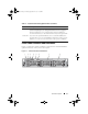
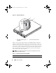
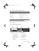
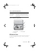
Table Of Contents
- Hardware Owner’s Manual
- About Your System
- Using the System Setup Program
- Installing System Components
- Recommended Tools
- Inside the System
- Front Bezel
- Opening and Closing the System
- Hard Drives
- Replacing a Hard-Drive Carrier
- Power Supplies
- System Fans
- Cooling Shroud
- Fan Brackets
- Cable Routing
- SAS Controller Daughter Card
- Configuring the Boot Device
- Expansion Cards
- Expansion-Card Cage
- DRAC Card and Cables
- Optical Drive and Cable
- System Memory
- Activating the Integrated NIC TOE
- Processors
- System Battery
- Expansion-Card Riser Boards
- Sideplane Board
- SAS Backplane Board
- Control Panel Assembly (Service-only Procedure)
- System Board (Service-only Procedure)
- Troubleshooting Your System
- Safety First-For You and Your System
- Start-Up Routine
- Checking the Equipment
- Troubleshooting Basic I/O Functions
- Troubleshooting a NIC
- Troubleshooting a Wet System
- Troubleshooting a Damaged System
- Troubleshooting the System Battery
- Troubleshooting Power Supplies
- Troubleshooting System Cooling Problems
- Troubleshooting System Memory
- Troubleshooting an Optical Drive
- Troubleshooting an External SCSI Tape Drive
- Troubleshooting a Hard Drive
- Troubleshooting a SAS Controller Daughter Card
- Troubleshooting Expansion Cards
- Troubleshooting the Microprocessors
- Running the System Diagnostics
- Jumpers and Connectors
- Getting Help
- Glossary
- Index

18 About Your System
Connecting External Devices
When connecting external devices to your system, follow these guidelines:
• Most devices must be connected to a specific connector and device drivers
must be installed before the device operates properly. (Device drivers are
normally included with your operating system software or with the device
itself.) See the documentation that accompanied the device for specific
installation and configuration instructions.
• Always attach external devices while your system and the device are turned off.
Next, turn on any external devices before turning on the system
(unless the documentation for the device specifies otherwise).
For information about individual connectors, see "Jumpers and Connectors"
on page 157. For information about enabling, disabling, and configuring
I/O ports and connectors, see "Using the System Setup Program" on page 45.
Power Indicator Codes
The power button on the front panel controls the power input to the system's
power supplies. The power indicator lights green when the system is on.
The indicators on the redundant power supplies show whether power is
present or whether a power fault has occurred (see Figure 1-4). Table 1-4 lists
the power supply indicator codes.
11 video connector 12 serial connector
13 Dell remote access controller
(optional)
Book.book Page 18 Monday, September 14, 2009 12:57 PM