
Storage System Hardware Owner's Manual
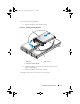
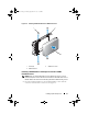
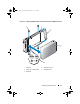
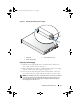
Table Of Contents
- Hardware Owner’s Manual
- About Your System
- Using the System Setup Program
- Installing System Components
- Recommended Tools
- Inside the System
- Front Bezel
- Opening and Closing the System
- Hard Drives
- Replacing a Hard-Drive Carrier
- Power Supplies
- System Fans
- Cooling Shroud
- Fan Brackets
- Cable Routing
- SAS Controller Daughter Card
- Configuring the Boot Device
- Expansion Cards
- Expansion-Card Cage
- DRAC Card and Cables
- Optical Drive and Cable
- System Memory
- Activating the Integrated NIC TOE
- Processors
- System Battery
- Expansion-Card Riser Boards
- Sideplane Board
- SAS Backplane Board
- Control Panel Assembly (Service-only Procedure)
- System Board (Service-only Procedure)
- Troubleshooting Your System
- Safety First-For You and Your System
- Start-Up Routine
- Checking the Equipment
- Troubleshooting Basic I/O Functions
- Troubleshooting a NIC
- Troubleshooting a Wet System
- Troubleshooting a Damaged System
- Troubleshooting the System Battery
- Troubleshooting Power Supplies
- Troubleshooting System Cooling Problems
- Troubleshooting System Memory
- Troubleshooting an Optical Drive
- Troubleshooting an External SCSI Tape Drive
- Troubleshooting a Hard Drive
- Troubleshooting a SAS Controller Daughter Card
- Troubleshooting Expansion Cards
- Troubleshooting the Microprocessors
- Running the System Diagnostics
- Jumpers and Connectors
- Getting Help
- Glossary
- Index
80 Installing System Components
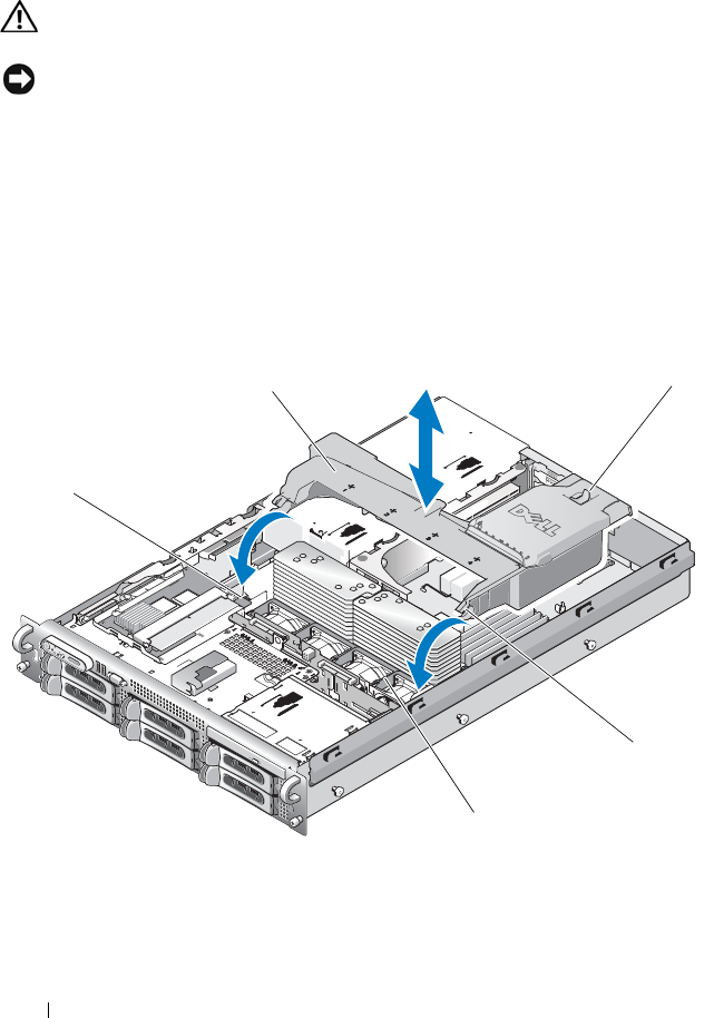
Cooling Shroud
The cooling shroud produces and directs airflow over the system memory modules.
CAUTION: The DIMMs are hot to the touch for some time after the system has
been powered down. Allow the DIMMs to cool before handling them.
NOTICE: Never operate your system with the memory cooling shroud removed.
Overheating of the system can develop quickly resulting in a shutdown of the
system and the loss of data.
Removing the Cooling Shroud
1
The cooling shroud is secured with a latch at the end of the shroud. Release
the latch by pulling it towards the outside wall of the chassis. See Figure 3-9.
2
Rotate the shroud upward and toward the front of the system on its hinges,
and then lift the shroud out of the system.
Figure 3-9. Removing and Installing the Cooling Shroud
1 shroud pivots (2) 2 cooling shroud
3 release latch 4 shroud hinges (2)
5 fan bracket
1
3
4
2
5
Book.book Page 80 Monday, September 14, 2009 12:57 PM