
Storage System Hardware Owner's Manual
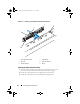
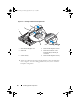
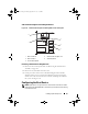
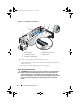
Table Of Contents
- Hardware Owner’s Manual
- About Your System
- Using the System Setup Program
- Installing System Components
- Recommended Tools
- Inside the System
- Front Bezel
- Opening and Closing the System
- Hard Drives
- Replacing a Hard-Drive Carrier
- Power Supplies
- System Fans
- Cooling Shroud
- Fan Brackets
- Cable Routing
- SAS Controller Daughter Card
- Configuring the Boot Device
- Expansion Cards
- Expansion-Card Cage
- DRAC Card and Cables
- Optical Drive and Cable
- System Memory
- Activating the Integrated NIC TOE
- Processors
- System Battery
- Expansion-Card Riser Boards
- Sideplane Board
- SAS Backplane Board
- Control Panel Assembly (Service-only Procedure)
- System Board (Service-only Procedure)
- Troubleshooting Your System
- Safety First-For You and Your System
- Start-Up Routine
- Checking the Equipment
- Troubleshooting Basic I/O Functions
- Troubleshooting a NIC
- Troubleshooting a Wet System
- Troubleshooting a Damaged System
- Troubleshooting the System Battery
- Troubleshooting Power Supplies
- Troubleshooting System Cooling Problems
- Troubleshooting System Memory
- Troubleshooting an Optical Drive
- Troubleshooting an External SCSI Tape Drive
- Troubleshooting a Hard Drive
- Troubleshooting a SAS Controller Daughter Card
- Troubleshooting Expansion Cards
- Troubleshooting the Microprocessors
- Running the System Diagnostics
- Jumpers and Connectors
- Getting Help
- Glossary
- Index

Installing System Components 83
Cable Routing
Cables that extend through the system front-to-back are routed along a cable
path within the interior right wall of the system chassis. The cables are
secured by a cable retention bracket that attaches to the inner wall.
Removing the Cable Retention Bracket
1
Remove the cooling shroud. See "Removing the Cooling Shroud."
2
Remove the cooling fan bracket. See "Removing the Fan Bracket."
3
Press outward on the blue release latch on the cable retention bracket and
slide the bracket back until the tabs at the bottom of the bracket clear the
chassis. See Figure 3-11.
4
Lift the cable retention bracket off the chassis wall.
Book.book Page 83 Monday, September 14, 2009 12:57 PM