
Storage System Hardware Owner's Manual
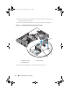
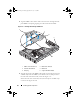
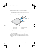
Table Of Contents
- Hardware Owner’s Manual
- About Your System
- Using the System Setup Program
- Installing System Components
- Recommended Tools
- Inside the System
- Front Bezel
- Opening and Closing the System
- Hard Drives
- Replacing a Hard-Drive Carrier
- Power Supplies
- System Fans
- Cooling Shroud
- Fan Brackets
- Cable Routing
- SAS Controller Daughter Card
- Configuring the Boot Device
- Expansion Cards
- Expansion-Card Cage
- DRAC Card and Cables
- Optical Drive and Cable
- System Memory
- Activating the Integrated NIC TOE
- Processors
- System Battery
- Expansion-Card Riser Boards
- Sideplane Board
- SAS Backplane Board
- Control Panel Assembly (Service-only Procedure)
- System Board (Service-only Procedure)
- Troubleshooting Your System
- Safety First-For You and Your System
- Start-Up Routine
- Checking the Equipment
- Troubleshooting Basic I/O Functions
- Troubleshooting a NIC
- Troubleshooting a Wet System
- Troubleshooting a Damaged System
- Troubleshooting the System Battery
- Troubleshooting Power Supplies
- Troubleshooting System Cooling Problems
- Troubleshooting System Memory
- Troubleshooting an Optical Drive
- Troubleshooting an External SCSI Tape Drive
- Troubleshooting a Hard Drive
- Troubleshooting a SAS Controller Daughter Card
- Troubleshooting Expansion Cards
- Troubleshooting the Microprocessors
- Running the System Diagnostics
- Jumpers and Connectors
- Getting Help
- Glossary
- Index
Installing System Components 97
4
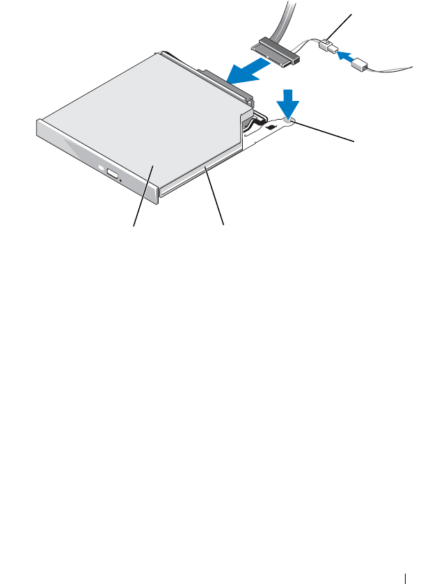
Disconnect the optical drive cable from the back of the drive.
5
To remove the optical drive, press down and forward on the blue tray
release tab and slide the drive tray out of the system. See Figure 3-17.
Figure 3-17. Removing and Installing the Optical Drive Tray
Installing the Optical Drive
1
Insert the optical drive tray into the system until it is fully inserted and
locked into position.
2
Connect the SATA cable (the end with the branching power cable) to the
back of the optical drive.
3
Connect the branching power cable to the power supply connector.
4
Remove the cooling shroud. See "Removing the Cooling Shroud" on
page 80.
1 optical-drive cable 2 optical-drive release tab
3 optical -drive tray 4 optical drive
2
4
3
1
Book.book Page 97 Monday, September 14, 2009 12:57 PM