
Storage System Hardware Owner's Manual
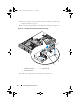
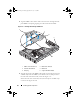
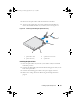
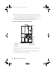
Table Of Contents
- Hardware Owner’s Manual
- About Your System
- Using the System Setup Program
- Installing System Components
- Recommended Tools
- Inside the System
- Front Bezel
- Opening and Closing the System
- Hard Drives
- Replacing a Hard-Drive Carrier
- Power Supplies
- System Fans
- Cooling Shroud
- Fan Brackets
- Cable Routing
- SAS Controller Daughter Card
- Configuring the Boot Device
- Expansion Cards
- Expansion-Card Cage
- DRAC Card and Cables
- Optical Drive and Cable
- System Memory
- Activating the Integrated NIC TOE
- Processors
- System Battery
- Expansion-Card Riser Boards
- Sideplane Board
- SAS Backplane Board
- Control Panel Assembly (Service-only Procedure)
- System Board (Service-only Procedure)
- Troubleshooting Your System
- Safety First-For You and Your System
- Start-Up Routine
- Checking the Equipment
- Troubleshooting Basic I/O Functions
- Troubleshooting a NIC
- Troubleshooting a Wet System
- Troubleshooting a Damaged System
- Troubleshooting the System Battery
- Troubleshooting Power Supplies
- Troubleshooting System Cooling Problems
- Troubleshooting System Memory
- Troubleshooting an Optical Drive
- Troubleshooting an External SCSI Tape Drive
- Troubleshooting a Hard Drive
- Troubleshooting a SAS Controller Daughter Card
- Troubleshooting Expansion Cards
- Troubleshooting the Microprocessors
- Running the System Diagnostics
- Jumpers and Connectors
- Getting Help
- Glossary
- Index

Installing System Components 99
Removing the Optical Drive Cable
CAUTION: Many repairs may only be done by a certified service technician. You
should only perform troubleshooting and simple repairs as authorized in your
product documentation, or as directed by the online or telephone service and
support team. Damage due to servicing that is not authorized by Dell is not covered
by your warranty. Read and follow the safety instructions that came with the
product.
1
Turn off the system, including any attached peripherals, and disconnect
the system from its electrical outlet.
2
Remove the bezel. See "Removing the Front Bezel" on page 65.
3
Open the system. See "Opening the System" on page 67.
4
Release the CD-to-side plane cable from the side plane by pressing
outward on the optical drive data cable ejectors until they reach the locked
position.
5
Remove the cable from the cable guides on the cooling shroud.
6
Remove the CD-to-side plane cable from the back of the optical drive. See
Figure 3-17.
Installing the Optical Drive Cable
1
Connect the CD-to-side plane cable (labeled CD) to the back of the
optical drive.
2
Route the cable on the side of the cooling shroud and then through the
cable guides on the cooling shroud.
3
With the optical drive data cable ejectors in the open position on the side
plane, insert the cable (labeled sideplane) into the connector until the
ejectors lock.
4
Close the system. See "Closing the System" on page 67.
5
Reconnect the system and peripherals to their power sources, and turn
them on.
Book.book Page 99 Monday, September 14, 2009 12:57 PM