DELL PowerVault LTO3-060 Tape Drive User's Guide TM TM The information below is provided by the supplier of the referenced device without independent verification by Dell and is subject to the restrictions and disclaimers noted below. Introduction Setting Up the Tape Drive Using the Tape Drive Using the Tape Backup Software Troubleshooting Specifications Glossary NOTE: A NOTE indicates important information that helps you make better use of your system.
Back to Contents Page Glossary: DELL PowerVault LTO3-060 Tape Drive User's Guide TM TM - A- B- C - D- E- F- G- H- I- J- L- M- N - O - P- R- S- T- U- V- W Numbers 2:1 compression. The relationship between the quantity of data that can be stored with compression as compared to the quantity of data that can be stored without compression. In 2:1 compression, twice as much data can be stored with compression as can be stored without compression. A A. See ampere. ampere (A).
D data. Any representations such as characters or analog quantities to which meaning is, or might be, assigned. data cartridge. A tape cartridge that is dedicated to storing data. Contrast with cleaning cartridge. data compression. See compression. data transfer rate. The average number of bits, characters, or blocks per unit of time that pass between corresponding equipment in a data transmission system. The rate is expressed in bits, characters, or blocks per second, minute, or hour. DC.
Generation 3. The informal name for the Ultrium 3 Tape Drive, which is the third-generation version of the Ultrium tape drive (Generation 1, 2). The Generation 3 drive has a native storage capacity of up to 400 GB per cartridge and a native sustained data transfer rate of 80 MB per second. gigabyte. 1,000,000,000 bytes. ground. An object that makes an electrical connection with the earth. H hardware. The physical equipment or devices that form a computer. head. See drive head.
the drive's head. log sense data. See SCSI log sense data. loop. (1) A series of instructions that is repeated until a terminating condition is reached. (2) To connect so as to complete a loop. Low Voltage Differential (LVD). A low-noise, low-power, and low-amplitude electrical signaling system that enables data communication between a supported server and the tape drive. LVD signaling uses two wires to drive one signal over copper wire. The use of wire pairs reduces electrical noise and crosstalk. LTO.
R read. To acquire or interpret data from a storage device, from a data medium, or from another source. reboot. To reinitialize the execution of a program by repeating the initial program load (IPL) operation. record. The smallest distinct set of data bytes that is supplied from a server for processing and recording by a tape drive, and the smallest distinct set of data to be read from tape, reprocessed, and made available to a server by a tape drive. relative humidity.
status light. Located at the front of the tape drive, an LED that can be green or amber, and (when lit) solid or flashing. The condition of the light represents the state of the drive. T TapeAlert. A patented technology and ANSI standard that defines conditions and problems that are experienced by tape drives. TapeAlert flags. Status and error messages that are generated by the TapeAlert utility and display on the server's console. tape cartridge.
Back to Contents Page Introduction: DELL PowerVault LTO3-060 Tape Drive User's Guide TM TM Overview SCSI Bus Interface Features Tape Backup Software Front Panel Rear Panel Status LEDs Operating Modes Unload Button Interpreting Operation Mode Status LEDs Overview The Dell PowerVault LTO3-060 is a high-performance, high-capacity tape storage device that is designed to backup and restore data and archive and retrieve files in an Open Systems environment.
The tape drive has the following features: l l l l l l l l l l l l l l l l l l Capacity of 400 GB (native), 800 GB (compressed*) on a single LTO tape Built-in read-after-write verification for a high level of data integrity Data transfer rate of 60 MB per second (native), 120 MB per second (compressed*) 128 MB of read/write cache memory Intelligent LTO-DC dual-mode compression algorithm Failsafe leader capture mechanism with pin pick error recovery LTO-Cartridge memory TapeAlert support for worry-free back
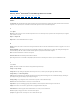
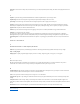
1. Power connector 2. SCSI ID connector 3. SCSI connector Status LEDs Each status LED has four modes: l l l l OFF ON Flashing slowly (at 2 Hz) Flashing rapidly (at 8 Hz) Operating Modes The drive functions in the following modes: l l Operation mode - functions include using data and cleaning cartridges, reporting errors and updating firmware. For more information, see Table 2. Interpretation of status LEDs in Operation mode (No Errors) below.
Cartridge Emergency Eject and Reset the drive Press and hold the Unload button on the drive for 12 seconds. The drive saves a dump of the current drive state to RAM, then reboots. After the reboot, the cartridge is slowly rewound to the beginning of tape (this may take some time). Another press of the unload button will eject the cartridge. Attention: Do not cycle power as this will erase the contents of the dump.
Back to Contents Page Setting Up the Tape Drive: DELL PowerVault LTO3-060 Tape Drive User's Guide TM TM Pre-installed Internal Drives Installing Internal Drives Loading Device Drivers Verifying Drive Operation Pre-installed Internal Drives Dell performs the installation and setup of internal tape drives that are shipped as part of a system. If tape backup software is included in your system, refer to the installation instructions included with the software.
Step 2 — Removing Power from the System 1. Power-off the system. 2. Disconnect the power cord from both the electrical outlet and the system. Step 3 — Setting the SCSI ID Your tape drive is shipped with a default SCSI ID of 6, but it can be assigned any unused ID between 0 and 15. Do not use SCSI ID 7, which is reserved for the SCSI controller, or SCSI ID 0, which is typically assigned to the boot disk. We do not recommend installing the drive onto a narrow SCSI bus, as this will restrict performance.
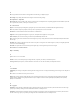
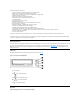
If your system does not use mounting hardware, check that the holes in the chassis are aligned with the holes in the side of the tape drive see Figure 7. Figure 7. Mounting Holes on Tape Drive 1. M-3 mounting screw holes Do not secure the drive with screws at this point because you may have to move the drive to get the cables in place. Step 7 — Attaching Power and SCSI Cables Attach a spare power cable from the system's internal power supply to the power connector, as shown in Figure 8, number 1.
1. Power connector 2. SCSI connector Step 8 — Securing the Drive The tape drive can be mounted several ways. Ensure that you have the proper mounting rails or drive mounting sled and the correct screws (M-3). Some systems require the drive to be inserted into a media bay and attached directly to the system. Figure 9. Secure the Drive Step 9 — Connecting Computer Power and Testing Power to the Tape Drive Connect the power cord to the system and to the electrical outlet.
Installation Procedures 1. Make sure that you are logged on to the host server or workstation with Administrator privileges. 2. Insert the Dell PowerVault LTO3-060 Drive Support CD into the CD drive on the host server or workstation. 3. Right-click the My Computer icon on the Windows desktop, click Manage, then click Device Manager. The tape drive should be listed under the ? Other Devices item as IBM Ultrium-HH3 SCSI Sequential Device. 4.
Back to Contents Page Using the Tape Backup Software: DELL PowerVault LTO3-060 Tape Drive User's Guide TM TM See the User's Operating Guide supplied with your Tape Backup application. For the latest supported software versions, go to support.dell.com or visit the support site of your backup software vendor Please read all restrictions and disclaimers.
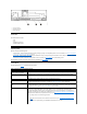
Back to Contents Page Specifications: DELL PowerVault LTO3-060 Tape Drive User's Guide TM TM General Manufacturer Manufactured for Dell Model Number DELL PowerVault LTO3-060 Internal Tape Drive Interface Type Ultra160 Low Voltage Differential (LVD) SCSI bus Physical Specifications Width (without bezel) 146.0 mm (5.75 in.) Width (with bezel) 148.0 mm (5.83 in.) Length (without bezel) 205.5 mm (8.09 in.) Length (with bezel) 210.5 mm (8.29 in.) Height (without bezel) 41.0 mm (1.6 in.
Back to Contents Page Troubleshooting: Dell PowerVault LTO3-060 Tape Drive User's Guide TM TM Obtaining Drivers and Firmware Upgrades Service Mode Working with Dumps Executing Service Functions General Guidelines Interpreting error conditions using status LEDs Methods of Receiving Errors and Messages Resolving Problems Reported by the System Resolving Media-Related Problems Removing a Tape Drive TapeAlert Manually Removing a Tape Cartridge Obtaining Drivers and Firmware Upgrades NOTICE: When updating fi
8 1 RESERVED for Trained Service Personnel Flashing rapidly ON ON Varies2 A blank data cartridge (scratch cartridge) is required for this function.
Important The drive will timeout if the next step is not performed within 15 seconds. 3. Insert a blank data cartridge (scratch cartridge). After a few minutes, the cartridge will unload, then load again. At the end of the self test, the drive will eject the cartridge. ¡ Refer to the chart below to determine if the test was successful or if it failed.
Key: = OFF = ON = Flashing slowly = Flashing rapidly Important The drive will timeout if the next step is not performed within 15 seconds. 3. Press the Unload Button 1 time to access Service Function 2. The status LEDs will be in one of the following states. Attention: If the Fault status LED is flashing slowly, a drive dump currently exists is RAM. Be aware that you will be overwriting the drive dump in RAM.
Key: = OFF = Flashing slowly = Flashing rapidly c. Verify that the Fault LED is flashing. n If the Fault LED is flashing, then the dump is in RAM. n If the Fault LED is not flashing, repeat the Service Function 2 procedure. d. Press the Unload button once per second until you exit from Service mode and the Ready light comes ON solid. Executing Service Function 3: Reserved for trained service personnel Executing Service Function 4: Copy dump to flash 1. Ensure there is no cartridge in the drive.
Key: = OFF = ON = Flashing slowly = Flashing rapidly 4. Double-click the Unload button to activate the service function. 5. The service function is complete when all drive status LEDs go off except for Ready, which will turn on solid. This indicates that the drive has exited service mode. 6. To verify that the dump is in flash memory, complete the following steps. a. Ensure there is no cartridge in the drive.
1. Ensure there is no cartridge in the drive. Note: If a cartridge is loaded in the drive, depression of the Unload button is interpreted as an unload request and the drive will ignore the second and third depressions. The drive cannot be put into Service mode while a cartridge is loaded. 2. Press and hold the Unload button until the Ready LED begins flashing rapidly indicating Service Function 1 has been accessed. The status LEDs will be in one of the following states.
4. Double-click the Unload button to activate the service function. 5. The service function is complete when all drive status LEDs go off except for Ready, which will turn on solid. This indicates that the drive has exited service mode. 6. To verify that the flash memory was erased, complete the following steps. a. Ensure there is no cartridge in the drive.
Connecting Computer Power and Testing Power to the Tape Drive). If the problem persists, replace the drive. The drive will not load a tape cartridge. One of the following has occurred: l l l l A tape cartridge is already inserted. To remove the cartridge, press the Unload button. If the cartridge does not eject, turn off the power to the drive, then turn it back on. After the Ready LED ( ) becomes solid ON, press the Unload button to eject the cartridge. The tape cartridge was inserted incorrectly.
If none of these actions corrects the problem, contact your customer support resource. 3 The Fault LED must be solid ON to indicate an over temperature condition. If a tape is present, it will be ejected.
¡ ¡ If the problem is with only one tape drive, do the following: n Replace the SCSI terminator and retry the failing operation. n Replace the SCSI cable and interposers, if any, and retry the failing operation. n If these measures do not correct the problem, contact Dell technical support. If the problem is with two or more tape drives, locate the first tape drive that has the error and replace the SCSI cable that connects the tape drive and the interposer (if installed).
0x2E. TapeAlert flags may appear as messages on the application screen or in the application error logs. TapeAlert Flags Table 5 lists the TapeAlert flags that are supported by the Dell PowerVault LTO3-060 Tape Drive. Table 5. TapeAlert Flags and Descriptions TapeAlert Flags Supported by the Tape Drive Flag Number Flag Parameter (in hex) 3 03h Hard error Set for any unrecoverable read, write, or positioning error. (This flag is set in conjunction with flags 4, 5, or 6.
1Fh Hardware B Set when the tape drive fails its internal self tests. Contact Dell support. 32 20h Interface Set when the tape drive detects a problem with the SCSI interface. Refer to "Resolving Problems Reported by the System." 33 21h Eject media Set when a failure occurs that requires you to unload the cartridge from the drive. Unload and reload the tape cartridge.
Back to Contents Page Using the Tape Drive: DELL PowerVault LTO3-060 Tape Drive User's Guide TM TM Operating the Drive Loading, Unloading and Write-Protecting Cartridges Caring for Tape Cartridges Cleaning the Tape Mechanism Operating the Drive The tape drive will come on when the system is powered on. The tape drive will run its Power-On Self-Test (POST). At the end of the hardware self-test, the Ready LED should be solid green.
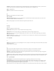
Figure 11 shows the LTO Ultrium 400-GB Data Cartridge and its components. Figure 11. LTO Ultrium 400-GB Data Cartridge 1. 2. 3. 4. 5. 6. LTO cartridge memory Label area Write-protect switch Insertion guide Cartridge door Leader pin Loading a Tape Cartridge 1. 2. 3. 4. Ensure that the tape drive is powered on (the Ready light is solid green). Ensure that the write-protect switch (see number 3 in Figure 11) is properly set. (See "Setting the Write-Protect Switch on Cartridges").
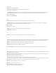
The position of the write-protect switch (number 1 in Figure 13) on the tape cartridge determines whether you can write to the tape: l l If the switch is set to locked (locked padlock), data cannot be written to the tape. If the switch is set to unlocked (unlocked padlock or black void), data can be written to the tape. Figure 13. Setting the Write-Protect Switch To set the switch, slide it left or right to the desired position.
2. Archival storage equals 1 to 10 years. Perform a Thorough Inspection l l l l l l l Inspect the cartridge's packaging to determine potential rough handling. When inspecting a cartridge, open only the cartridge door. Do not open any other part of the cartridge case. The upper and lower parts of the case are held together with screws; separating them destroys the usefulness of the cartridge. Inspect the cartridge for damage before using or storing it.