
Reference Guide


Understanding Your Failover Cluster 51
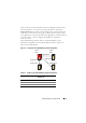
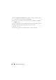
Table 4-7 shows a four-node multiway failover configuration for the cluster
shown in Figure 4-3. For each resource group, the failover order in the
Preferred Owners list in Failover Cluster Management console outlines the
order that you want that resource group to failover. In this example, node 1
owns applications A, B, and C. If node 1 fails, applications A, B, and C failover
to cluster nodes 2, 3, and 4. Configure the applications similarly on
nodes 2, 3, and 4.
When implementing multiway failover, configure failback to avoid
performance degradation. See "Understanding Your Failover Cluster" on
page 5 for more information.
Figure 4-3. Example of a Four-Node Multiway Failover Configuration
Table 4-7. Example of a Four-Node Multiway Failover Configuration
Application Failover Order in the Preferred
Owners List
ANode 2
BNode 3
CNode 4
cluster
node 1
cluster
node 2
cluster node 4 cluster node 3
application A
application B
application C