Dell PowerVault MD3800f and MD3820f Series Storage Arrays Deployment Guide
Notes, cautions, and warnings NOTE: A NOTE indicates important information that helps you make better use of your computer. CAUTION: A CAUTION indicates either potential damage to hardware or loss of data and tells you how to avoid the problem. WARNING: A WARNING indicates a potential for property damage, personal injury, or death. Copyright © 2016 Dell Inc. All rights reserved. This product is protected by U.S. and international copyright and intellectual property laws.
Contents 1 Introduction......................................................................................... 5 System Requirements................................................................................. 5 Management Station Requirements............................................................ 5 Introduction to Storage Arrays...................................................................... 5 Related Documentation............................................................................
Uninstalling MD Storage Software From Windows...............................................28 Uninstalling MD Storage Software From Windows Server GUI Versions................. 28 Uninstalling MD Storage Software From Windows Server Core Versions................ 28 Uninstalling MD Storage Software From Linux................................................... 29 6 Load Balancing.................................................................................... 30 Load Balance Policy........................
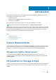
1 Introduction This document provides information about deploying Dell PowerVault MD3800f and MD3820f Fibre Channel storage arrays. The deployment process includes: • Hardware installation • Modular Disk Storage Manager (MDSM) software installation • Initial system configuration Other information includes system requirements, storage array organization, and utilities. NOTE: For more information on product documentation, see Dell.com/support/manuals.
One or more host servers attached to the storage array can access the data on the storage array. You can also establish multiple physical paths between the hosts and the storage array so that loss of any single path (for example, through failure of a host server port) does not result in loss of access to data on the storage array.
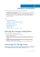
2 Hardware Installation Before using this guide, ensure that you review the instructions in the documents: • Getting Started Guide — The Getting Started Guide shipped with the storage array provides information to configure the initial setup of the system. • Planning section of the Owner’s Manual — The planning section provides information about important concepts to set up your storage solution. See the Owner’s Manual at Dell.com/support/manuals.
The functions of the ports on each controller are described below: • 16 gbps Fibre Channel Host Ports (4) — Allows you to connect host servers to the storage array. • 12 gpbs SAS Host Ports (2) — Allows you to connect host servers to the storage array. • 1 gbps Ethernet Management (MGMT) Port (1) — Management port allows for out of band management of storage array. • Reserved Ethernet Port (1) — Reserved.
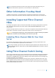
NOTE: All equipment attached to the switch must be powered on before establishing zoning. For additional switch hardware requirements, see the manufacturer’s documentation. Other Information You May Need In addition to this document, see the documentation provided with the HBA and Fibre Channel switch hardware for vendor-specific information required to complete Fibre-Channel setup on your storage array.
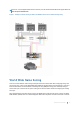
NOTE: For a list of supported Fibre Channel switches, see the Dell PowerVault MD Series Support Matrix at Dell.com/powervaultmanuals. Figure 1. Example of Switch Zoning on SAN on an MD38xxf-series Fibre-Channel Storage Array World Wide Name Zoning There are several different switch zoning techniques used across various SANs. When configuring zoning with your storage array, using a 64 bit World Wide Name (WWN) to uniquely identify each component in your Fibre Channel switch fabric is recommended.
the switch fabric. By zoning specific ports on the host server(s), switch and storage array together, the switch allows the host server to see only devices included in that zone, decreasing the amount of time it would otherwise take for the host server to query attached, but out-of-zone, devices.
removed cable, failed HBA, or failed or removed RAID controller module results in loss of host access to the storage array. Redundant configurations establish separate data paths between the host server(s) and storage array. Each path is connected to separate RAID controller modules in the storage array. Redundancy protects the host server(s) from losing access to data in the event of a path failure since both RAID controller modules can independently access all the physical disks in the storage array.
SAN-Attached Cabling Example The following figure shows a three-server, mixed HBA cabling configuration that uses two separate switch fabrics to establish multiple paths to the storage array. Port-to-port connections in each switch fabric or zone are detailed in the text boxes. Figure 2. Three SAN-Attached Host Servers Connected to a Storage Array Using Multiple Paths Table 1.
Switch Fabric A Switch Fabric B Array1_Ctrl-0-3 Array1_Ctrl-0-2 Array1_Ctrl-1-0 Array1_Ctrl-1-1 Array1_Ctrl-1-2 Array1_Ctrl-1-3 Zone2_Server2_HBA_0 Zone5_Server2_HBA_1 Server2_HBA_0 Server2_HBA_1 Array1_Ctrl-0-0 Array1_Ctrl-0-1 Array1_Ctrl-0-3 Array1_Ctrl-0-2 Array1_Ctrl-1-0 Array1_Ctrl-1-1 Array1_Ctrl-1-2 Array1_Ctrl-1-3 Zone3_Server3_HBA_0 Zone6_Server3_HBA_1 Server3_HBA_0 Server3_HBA_1 Array1_Ctrl-0-0 Array1_Ctrl-0-1 Array1_Ctrl-0-3 Array1_Ctrl-0-2 Array1_Ctrl-1-0 Array1_Ctrl
reserved exclusively for Remote Replication traffic. No other data traffic is allowed on that port until the Remote Replication feature is deactivated. A dedicated zone on each Fibre Channel switch is also required. Figure 3. Remote Replication Cabling Table 2.
Switch Fabric A Switch Fabric B Array1_Ctrl-0-0 Array1_Ctrl-0-1 Array1_Ctrl-1-0 Array1_Ctrl-0-2 Array1_Ctrl-1-2 Array1_Ctrl-1-1 Zone4_Server3_HBA_0_1 Zone9_Server3_HBA_0_0 Server3_HBA_0_1 Server3_HBA_0_0 Array2_Ctrl-0-1 Array2_Ctrl-0-0 Array2_Ctrl-0-2 Array2_Ctrl-1-0 Array2_Ctrl-1-1 Array2_Ctrl-1-2 Zone5_Server3_HBA_1_1 Zone10_Server3_HBA_1_0 Server3_HBA_1_1 Server3_HBA_1_0 Array2_Ctrl-0-1 Array2_Ctrl-0-0 Array2_Ctrl-0-2 Array2_Ctrl-1-0 Array2_Ctrl-1-1 Array2_Ctrl-1-2 Replication
Mixed Environment The following figure shows mixed configuration, that is SAS direct attached and host connectivity via the SAN (that is FC or Ethernet switch). Figure 4. Mixed Environment NOTE: The SAS host ports in the PowerVault MD3800f and MD3820f storage arrays are recommended to be connected to a secondary host or backup network.
Cabling PowerVault MD1200 Series Expansion Enclosures You can expand the capacity of your PowerVault MD3800i and MD3820i series storage array by adding PowerVault MD1200 series expansion enclosures. You can expand the physical disk pool to a maximum of 120 (or 192, if enabled using Premium Feature activation) physical disks using a maximum of seven expansion enclosures.
NOTE: To connect the MD1200 expansion enclosure to your MD Series high-capacity RAID storage array, refer to the following diagrams shown here. Figure 5. Single expansion cabling diagram Figure 6.
Expanding With Previously Configured PowerVault MD1200 Series Expansion Enclosures Use this procedure if your expansion enclosure is directly attached and configured with a Dell PowerEdge RAID Controller (PERC) H800 adapter. Data from virtual disks created on a PERC H800 adapter cannot be directly migrated to a storage array or an expansion enclosure connected to a storage array.
Expanding With New PowerVault MD1200 Series Expansion Enclosures Perform the following steps to attach new PowerVault MD1200 series expansion enclosures to a PowerVault MD34xx/38xx series storage arrays: 1 Before adding the expansion enclosures, ensure that the storage array software is installed and is up to date. For more information, see the Dell PowerVault MD34xx/38xx Support Matrix at Dell.com/support/ manuals.
3 Installing PowerVault MD Storage Software The Dell PowerVault MD series resource media contains software and drivers for both Linux and Microsoft Windows operating systems. The root of the media contains a readme.txt file covering changes to the software, updates, fixes, patches, and other important data applicable to both Linux and Windows operating systems. The readme.
Topics: • Installing Host Bus Adapters and Drivers • Graphical Installation (Recommended) • Console Installation • Silent Installation • Enabling Premium Features (Optional) • Upgrading MD Storage Software Installing Host Bus Adapters and Drivers Ensure that you read the Configuring Fibre Channel With the Dell PowerVault MD Series Storage Arrays document before continuing with this procedure. 1 Install the host bus adapters (HBAs). 2 Connect the cables.
NOTE: The MD Storage Manager installer automatically installs the required drivers, firmware, and operating system patches/hotfixes to operate your storage array. These drivers and firmware are also available at Dell.com/support. In addition, see the Dell PowerVault MD34xx/38xx Series Support Matrix at Dell.com/support/manuals for any additional settings and/or software required for your specific storage array.
Enabling Premium Features (Optional) If you ordered premium features, follow the instructions on the Premium Features card to install the additional features. Upgrading MD Storage Software To upgrade from a previous version of the MDSM application, uninstall the previous version (see the Uninstalling MD Storage Software section), and then follow the instructions in this chapter to install the new version.
4 Post Installation Tasks Before using the Dell PowerVault storage array for the first time, complete these initial configuration tasks in the order shown. These tasks are performed using the MD Storage Manager (MDSM) software. 1 For out-of-band management, you must set the network configuration for each RAID controller module, including its Internet Protocol (IP) address, subnetwork mask (subnet mask), and gateway. NOTE: You can set the network configuration using a DHCP server 2 3 Start MDSM.
Initial Setup Tasks Enter the context of your task here (optional). This is where introductory content goes. 1 The name of the first storage array found is displayed in the Devices tab of the EMW. To see a list of all storage arrays found on the local network, expand the discovered storage arrays tab in the Device pane of the EMW. 2 The default name for a newly installed MDxxxxx series storage array is Unnamed.
5 Uninstalling MD Storage Software Uninstalling MD Storage Software From Windows 1 From the Control Panel, double-click Add or Remove Programs. 2 Select MD Storage Software from the list of programs. 3 Click Change/Remove. The Uninstall Complete window is displayed. 4 Follow the instructions on screen. 5 Select Yes to restart the system, and then click Done. Uninstalling MD Storage Software From Windows Server GUI Versions 1 From the Control Panel, double-click Programs and Features.
Uninstalling MD Storage Software From Linux 1 By default, MD Storage Manager is installed in the /opt/dell/mdstoragemanager directory. If another directory was used during installation, navigate to that directory before beginning the uninstallation procedure. 2 From the installation directory, open the Uninstall Dell MD Storage Software directory and run the file Uninstall Dell MD Storage Software.exe. When the uninstallation is complete, it goes back to the root prompt.
6 Load Balancing Load Balance Policy Multi-path drivers select the I/O path to a virtual disk through a specific RAID controller module. When the multi-path driver receives a new I/O to process, the driver tries to find a path to the current RAID controller module that owns the virtual disk. If the path to the current RAID controller module that owns the virtual disk cannot be found, the multi-path driver migrates the virtual disk ownership to the secondary RAID controller module.
Least Path Weight The least path weight policy assigns a weight factor to each data path to a virtual disk. An I/O request is routed to the path with the lowest weight value to the RAID controller module that owns the virtual disk. If more than one data path to the virtual disk has the same weight value, the round robin with subset path selection policy is used to route I/O requests between the paths with the same weight value.
Setting Load Balance Policies in VMware VMware supports Asymmetric Logical Unit Access (ALUA). For more information on Most Recently Used (MRU) and Round Robin (RR) load balancing policies, see VMware documents.
7 Working With SFP+ Modules and Fiber Optic Cables Each storage controller can have up to four FC host ports. A small-form-factor pluggable (SFP+) module is used to connect a host port to a host or switch. The SFP+ module is inserted into the port, and then a fiber optic cable is inserted into the SFP+ module. The other end of the fiber optic cable is connected to an optical interface connector either in a FC HBA on a host or a switch. SFP+ modules are laser products.
Removing SFP+ Modules To remove SFP+ modules: 1 Remove the FC cable from the SFP+ module. See Working With SFP+ Modules and Fiber Optic Cables 2 Unlock the SFP+ module latch. For SFP+ modules that contain wire tabs, unlock the SFP+ module latch by pulling the wire latch outward 90°. 3 With the SFP+ module latch in the unlocked position, remove the SFP+ module. For SFP+ modules that contain wire tabs, grasp the wire latch and pull the SFP+ module out of the port.
3 While pressing down the cable lever, pull the connector to remove the cable from the SFP+ module. 4 Replace the protective caps on the cable ends. 5 Replace the protective cap on the SFP+ module. Installing Fibre Channel Cables WARNING: Data processing environments can contain equipment transmitting on system links with laser modules that operate at greater than Class 1 power levels. Never look into the end of an optical fiber cable or open receptacle.
8 Hardware Cabling Best Practices Handling Static-Sensitive Components Static electricity can damage memory modules, system boards, and other static-sensitive components. To prevent damaging the system, follow these precautions: • Move and store all components in the static-protective packaging. • Place components on a grounded surface before removing them from their static-protective packaging. • Grounded surfaces include static-dissipating mats or grounded workstations.
Single-Controller and Dual-Controller Topologies While creating a topology for a RAID enclosure that contains only one RAID controller module, attach expansion enclosures that contain only one single enclosure management module (EMM). Do not attach an expansion enclosure that contains two EMMs to a single-controller RAID enclosure. Labeling Cables Cabling is an important part of creating a robust storage array. Labeling the cables identifies system components and drive channels.
9 Getting help Topics: • Contacting Dell • Locating your Dell system Service Tag Contacting Dell Dell provides several online and telephone-based support and service options. If you do not have an active internet connection, you can find contact information on your purchase invoice, packing slip, bill, or Dell product catalog. Availability varies by country and product, and some services may not be available in your area.