
Deployment Guide


the switch fabric. By zoning specific ports on the host server(s), switch and storage array together, the switch
allows the host server to see only devices included in that zone, decreasing the amount of time it would
otherwise take for the host server to query attached, but out-of-zone, devices.
Switch Zoning Guidelines
The storage array imposes specific requirements that must be followed when setting up Fibre Channel switch
zoning:
• If a Fibre Channel switch is used to connect your host server and storage array, it must be zoned. Un-
zoned or open switches cannot be used.
• WWN port zoning is recommended. While hard zoning (zoning by device ID) is supported, LUN masking
uses the WWN identifier. You can mix WWN and hard-zoned ports in the same zone.
• Multi-port HBAs are supported. Each port in a multiple-port HBA represents one initiator. Each initiator
must be connected to a single logical switch zone.
• No more than four paths (port-to-port segments) can be established from a single, physical host server(s)
to a single RAID controller.
• A zone can contain multiple targets and span multiple storage arrays (single initiator can point to
multiple targets).
NOTE: To simplify troubleshooting, you can assign a single initiator and single target to a zone.
• If the Remote Replication premium feature is activated, a separate zone for each replication port is
required. Only data traffic related to Remote Replication can move through that zone. For more details
and requirements regarding Remote Replication, see the Dell PowerVault MD Series Storage Arrays
Administrator's Guide at Dell.com/powervaultmanuals.
Setting Up Zoning On The Fibre Channel Switch
Hardware
Setting up zoning on Fibre Channel switches varies greatly between manufacturers. For detailed information
on how to set up zoning on your switch, see the manufacturer’s product documentation or technical support
website.
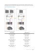
Cabling The Storage Array
Cabling the storage array depends on a number of factors such as:
• Required level of redundancy or throughput
• Number of host servers connected to the storage array
• Type of HBAs (dual- or single-port) used in the host server(s)
• Remote Replication premium feature (if applicable)
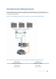
The cabling diagrams shown here do not represent every supported cabling scenario but the concepts of
redundancy and switch logic can be used to build your own configuration.
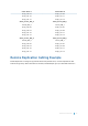
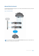
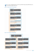
Redundant And Non-Redundant Cabling
Non-redundant cabling configurations provide a single data path from host server(s) to the storage array. This
type of configuration is only recommended for non-critical data storage. A path failure from a failed or
Hardware Installation 11