Dell EMC PowerVault MD3860f Series Storage Arrays Deployment Guide February 2018 Rev.
Notes, cautions, and warnings NOTE: A NOTE indicates important information that helps you make better use of your product. CAUTION: A CAUTION indicates either potential damage to hardware or loss of data and tells you how to avoid the problem. WARNING: A WARNING indicates a potential for property damage, personal injury, or death. © 2012 - 2018 Dell Inc. or its subsidiaries. All rights reserved. Dell, EMC, and other trademarks are trademarks of Dell Inc. or its subsidiaries.
Contents Chapter 1: Introduction................................................................................................................. 5 System requirements..........................................................................................................................................................5 Introduction to storage arrays..........................................................................................................................................
Uninstalling MD Storage Manager from Linux........................................................................................................... 25 Chapter 6: Load balancing........................................................................................................... 26 Load balance policy...........................................................................................................................................................26 Round robin with subset.......................
1 Introduction This guide provides information about deploying Dell EMC PowerVault MD3860f storage arrays. The deployment process includes: ● Hardware installation ● Modular Disk Storage Manager (MD Storage Manager) installation ● Initial system configuration Other information provided include system requirements, storage array organization, and utilities. NOTE: For more information on product documentation, see Related Documentation.
Unconfigured capacity comprises physical disks not already assigned to a disk group or DDP. When a virtual disk is created using unconfigured capacity, a disk group is automatically created. If the only virtual disk in a disk group is deleted, the disk group is also deleted. Free capacity is space in a disk group that is not assigned to any virtual disk. Data is written to the physical disks in the storage array using RAID technology. RAID levels define how data is written to physical disks.
2 Hardware installation Before using this guide, ensure that you review the instructions in the: ● Dell PowerVault MD3460/MD3860i/MD3860f Storage Arrays Getting Started Guide — The Getting Started Guide that is shipped with the storage array provides information to configure the initial setup of the system. ● Dell PowerVault MD Series Storage Arrays Administrator's Guide — The Administrator's Guide provides information about important concepts you must know before setting up your storage solution.
Configuring Fibre Channel with Dell EMC MD Series storage arrays This section provides information about configuring Fibre Channel communication between the host server and the storage array. For basic setup information such as racking, power cabling, and recommended handling procedures, see the Getting Started Guide for your storage array at Dell.com/powervaultmanuals.
CAUTION: Connecting the storage array to a nonsupported host server HBA or installing nonqualified HBA drivers or firmware can cause instability or loss of access to your data. Installing Fibre Channel HBA on your host server For instructions about physically installing an HBA in your host server and loading supported drivers and firmware, see the documentation supplied with your HBA hardware. NOTE: During installation you must enter the manufacturer-specific timeout and/or node time values.
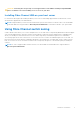
Figure 1. Example of switch zoning on SAN on MD38xxf-series Fibre-Channel storage array World Wide Name zoning There are several different switch zoning techniques used across various SANs. When configuring zoning with your storage array, using a 64 bit World Wide Name (WWN) to uniquely identify each component in your Fibre Channel switch fabric is recommended.
● WWN port zoning is recommended. While hard zoning is supported, LUN masking uses the WWN identifier. You can mix WWN and hard-zoned ports in the same zone. ● Multiport HBAs are supported. Each port in a multiple-port HBA represents one initiator. Each initiator must be connected to a single logical switch zone. ● No more than four paths (port-to-port segments) can be established from a single, physical host server(s) to a single RAID controller.
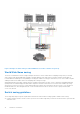
Figure 2. Three SAN-attached host servers connected to a storage array using multiple paths Table 1.
Table 1.
Table 2.
Figure 4. Mixed environment NOTE: The SAS host ports in the PowerVault MD3860f storage array is recommended to be connected to a secondary host or backup network. Cabling PowerVault MD3060e expansion enclosures You can expand the capacity of your PowerVault MD3860f Series storage array by adding PowerVault MD3060e expansion enclosures.
MD3060e expansion cabling diagrams Figure 5.
Figure 6. Dual expansion diagram Expanding with new PowerVault MD3060e expansion enclosures NOTE: Hot plug of MD3060e expansion enclosure is not recommended. Power on all MD3060e expansion enclosures before you power on the array enclosure. For helpful videos and other resources on PowerVault MD series, see dell.com/ PVresources. Perform the following steps to attach new PowerVault MD3060e expansion enclosures to a PowerVault MD3860f Series storage array: 1.
7. Turn off any expansion enclosure(s) in the affected system. 8. Cable the expansion enclosure(s) to the storage array. For correct cabling diagrams, see "Cabling PowerVault MD3060e Expansion Enclosure" earlier in this guide. 9. Turn on the expansion enclosure(s) and wait for the enclosure status LED to turn blue. 10. Turn on the storage array and wait for the status LED to indicate that the unit is ready: ● When power is on, the power on indicator lights solid green.
3 Installing MD Storage Manager The PowerVault MD Series resource media contains software and drivers for both Linux and Microsoft Windows operating systems. The root of the media contains a readme.txt file describing changes to the software, updates, fixes, patches, and other important data applicable to both Linux and Windows operating systems. The readme.
Installing host bus adapters and drivers 1. Install the host bus adapters (HBAs). 2. Connect the cables. 3. Install the HBA drivers and the operating system HBA patches/hotfixes. 4. Ensure that the recommended HBA settings are applied. Graphical installation (recommended) The MD Storage Manager configures, manages, and monitors the storage array. To install the MD storage manager: 1. Insert the PowerVault MD Series resource media. Depending on your operating system, the installer may launch automatically.
Console installation NOTE: Console installation only applies to Linux systems that are not running a graphical environment. The autorun script in the root of the resource media detects when there is no graphical environment running and automatically starts the installer in a text‑based mode. This mode provides the same options as graphical installation. Silent installation Silent installation on Windows To run silent installation on a Windows system: 1. Copy the custom_silent.
4 Post installation tasks Before using the Dell PowerVault storage array for the first time, complete these initial configuration tasks in the order shown. These tasks are performed using the MD Storage Manager. 1. For out-of-band management, you must set the network configuration for each RAID controller module, including its Internet Protocol (IP) address, subnetwork mask (subnet mask), and gateway. NOTE: You can set the network configuration using a DHCP server. 2. Launch MD Storage Manager.
Initial setup tasks 1. The name of the first storage array found is displayed in the Devices tab of the EMW. To see a list of all storage arrays found on the local network, expand Discovered Storage Arrays in the Devices tab of the EMW. 2. The default name for a newly installed PowerVault MD3860f series storage array is Unnamed. another name is displayed in MD Storage Manager, click the down arrow next to the name and click Unnamed in the drop-down list and rename the array. 3.
5 Uninstalling MD Storage Manager Topics: • • • • Uninstalling MD Storage Manager from Windows Uninstall MD Storage Manager from Windows Server GUI version Uninstall MD Storage Manager on Windows Server Core versions Uninstalling MD Storage Manager from Linux Uninstalling MD Storage Manager from Windows To uninstall the Modular Disk Storage Manager from Microsoft Windows Server: 1. Double-click Add or Remove Programs from the Control Panel. 2. Select Dell MD Storage Software from the list of programs. 3.
Uninstalling MD Storage Manager from Linux By default, PowerVault MD Storage Manager is installed in the /opt/dell/mdstoragemanager directory. If another directory was used during installation, navigate to that directory before beginning the uninstallation procedure. 1. From the installation directory, open the Uninstall Dell MD Storage Software directory. 2. Run the file Uninstall Dell MD Storage Software.exe. 3. From the Uninstall window, click Next, and follow the instructions on the screen.
6 Load balancing Topics: • • • Load balance policy Setting load balance policies in Linux Setting load balance policies in VMware Load balance policy Multi-path drivers select the I/O path to a virtual disk through a specific RAID controller module. When the multi-path driver receives a new I/O to process, the driver tries to find a path to the current RAID controller module that owns the virtual disk.
Setting load balance policies in Linux Linux only supports round robin based load balancing. For more information, see Round robin with subset on page 26. Setting load balance policies in VMware VMware supports Asymmetric Logical Unit Access (ALUA). For more information on Most Recently Used (MRU) and Round Robin (RR) load balancing policies, see VMware documents.
7 Appendix — Working with SFP modules and fiber optic cables Each storage controller can have up to four FC host ports. A small-form-factor pluggable (SFP) module is used to connect a host port to a host or switch. The SFP module is inserted into the port, and then a fiber optic cable is inserted into the SFP module. The other end of the fiber optic cable is connected to an optical interface connector either in a FC HBA on a host or a switch. SFP modules are laser products.
Figure 7. Installing and removing an SFP module 1. FC IN slot (4) 3. fibre optic cable 2. SFP+ transceiver 4. gate Removing SFP modules To remove SFP modules: 1. Remove the FC cable from the SFP module. See Removing Fibre Channel Cables. NOTE: To avoid damaging the cable or the SFP module, disconnect the FC cable before removing the SFP module. 2. Unlock the SFP module latch. For SFP modules that contain wire tabs, unlock the SFP module latch by pulling the wire latch outward. 3.
To install an FC cable: 1. If applicable, remove the protective cap from the SFP module and store the protective cap for future use. 2. Remove the two protective caps from one end of the cable and store them for future use. 3. Insert the cable into an SFP module that is installed in the storage array. The cable connector is keyed for correct installation. Holding the connector, push in the cable until it clicks into place. 4.
8 Appendix — Hardware cabling best practices Topics: • • • • Handling static sensitive components Host cabling for Remote Replication Cabling for performance Labeling cables Handling static sensitive components Static electricity can damage memory modules, system boards, and other static-sensitive components. To prevent damaging the system, follow these precautions: ● ● ● ● Move and store all components in the static-protective packaging.
If a component fails, the cables must be disconnected, the failed component replaced, and the cables reattached. Detailed labeling of the cables simplifies the component replacement process. If you are adding a new expansion enclosure to an existing configuration, correctly labeled cables help identify where to connect the new enclosure.
9 Getting help Topics: • • Contacting Dell Locating your Dell EMC system service tag Contacting Dell Dell provides several online and telephone based support and service options. If you do not have an active internet connection, you can find contact information about your purchase invoice, packing slip, bill, or Dell product catalog. Availability varies by country and product, and some services may not be available in your area.