Dell PowerVault MD3860f Storage Arrays Owner's Manual Regulatory Model: E08J Series Regulatory Type: E08J001
Notes, Cautions, and Warnings NOTE: A NOTE indicates important information that helps you make better use of your computer. CAUTION: A CAUTION indicates either potential damage to hardware or loss of data and tells you how to avoid the problem. WARNING: A WARNING indicates a potential for property damage, personal injury, or death. Copyright © 2015 Dell Inc. All rights reserved. This product is protected by U.S. and international copyright and intellectual property laws.
Contents 1 About your system................................................................................................ 6 Introduction...........................................................................................................................................6 Dell PowerVault Modular Disk Storage Manager ................................................................................ 6 Related Documentation...................................................................................
Removing A Physical Disk From A Physical-Disk Drawer............................................................30 Installing A Physical Disk In A Physical-Disk Drawer.................................................................... 31 SAS Chain Cables.................................................................................................................................31 Removing The SAS Chain Cable(s)..............................................................................................
ECC Errors..................................................................................................................................... 50 PCI Errors.......................................................................................................................................50 5 Technical Specifications.................................................................................... 51 6 Getting help........................................................................................
About your system 1 Introduction CAUTION: See the Safety, Environmental, and Regulatory Information document for important safety information before following any procedures listed in this document. The Dell PowerVault MD3860f RAID storage array (16 Gbps Fibre Channel) is a 4U rack-mounted system, capable of accommodating up to sixty 3.5 inch or 2.5 inch physical disks.
• Dell PowerVault MD Series Storage Arrays Administrator's Guide — Provides information about configuring and managing the system using the MDSM GUI. • Dell PowerVault MD Series Storage Arrays CLI Guide — Provides information about configuring and managing the system using the MDSM CLI. • Dell PowerVault MD3860f Series Storage Arrays Deployment Guide — Provides information about deploying the storage system in the SAN architecture.
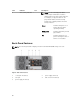
Front-Panel Indicators Figure 2. Front-Bezel Indicators Figure 3.
Item Indicator Icon Description 1 Power-on indicator The power-on indicator lights green when at least one power supply module is supplying power to the storage enclosure. 2 Standby power indicator The standby power indicator lights green when the system is in standby mode and the main power is off. 3 System identification indicator The system identification indicator lights white and helps locate a particular enclosure within a rack.
Item Indicator 8 Drive activity indicator Icon Description NOTE: The associated physical disk is indicated by a number (0 to 11) that is displayed above the drive activity indicator. For example, for physical disk 2 on the physical disk drawer, the drive activity indicator has 2 displayed above the drive activity indicator. Green Indicates that power is on and the physical disk is operating normally. Blinks green Indicates I/O activity for that physical disk.
Cooling Fan Module LED Indicator Codes Figure 5. Cooling Fan Module Indicators Item Indicator Icon Description 1 Power indicator The power indicator lights green when power to the cooling fan module is available. 2 Service action required indicator The Service action required indicator lights amber when there is a fault in the cooling fan module. 3 Service action allowed indicator CAUTION: Remove the cooling fan module from the system only if the Service action allowed indicator lights blue.
Power Supply Module Features And Indicators NOTE: Your storage array is shipped with two IEC C19 to C20 jumper cords. Connect the C19 plug to the array's power supplies and the C20 plug to the power distribution unit (PDU) in the rack cabinet. Figure 6. Power Supply Module Features and Status Indicators Item Indicator or Connector 1 Power connector Connect the external power supply source to this connector. 2 Power switch The power switch controls the power supply output to the system.
Item Indicator or Connector Icon Description Off 6 Service action required indicator 7 AC power indicator Indicates that you cannot remove the power supply module from the system. The service action required indicator lights amber when there is a fault in the power supply module. Green Indicates that AC output voltage is within the limit. Off Indicates that AC output voltage is not within the limit. Physical-Disk LED Indicators Figure 7.
Item Indicator 1 Service action allowed indicator 2 14 Service action required indicator Icon Description CAUTION: Remove the physical disk from the system only if the service action allowed indicator lights blue. Removing the physical disk from the system when the service action allowed indicator is off may damage the system. Blue Indicates that you can safely remove the physical disk from the system. Off Indicates that you cannot remove the physical disk from the system.
Controller Modules 2 RAID Controller Modules RAID controller modules provide high-performance, advanced virtual disk configuration, and faulttolerant disk subsystem management. Each RAID controller module contains 4 GB of mirrored cache for high availability and is protected by a battery powered cache offload mechanism. NOTE: 8 GB mirrored cache is an optional feature.
Item Indicator, Button, or Connector Icon Description 3 12 Gbps SAS IN port (2) Provides host-to-controller SAS connection. 4 USB port Reserved port. 5 Mini USB port Dell support only. 6 Password reset switch Pressing this switch resets the password. 7 SAS expansion port (2) Provides SAS OUT connection for cabling to a daisy chained expansion enclosure. Port 0 expansion port is recommended. 8 16 Gbps FC IN port (4) Provides host-to-controller SAS connection.
SFP+ Transceivers Fibre Optic And SAS Cables NOTE: Your small form-factor pluggable (SFP+) transceivers and cables may look different from the ones shown below. The differences do not affect the performance of the SFP+ transceivers. FC host connections may operate at 4 Gbps, 8 Gbps, or 16 Gbps. Ports for 16 Gbps Fibre Channel host connections require SFP+ transceivers designed for this data rate. SFP+ transceivers that support other data rates are incompatible.
Figure 10. SAS Cable 1. mini SAS connector 3. mini SAS HD connector 2. SAS cable Expansion Controller Modules Use the expansion controller modules to expand the storage capacity up to a maximum of 120 disks (180 disks with premium feature), by daisy-chaining your storage enclosure with up to two MD3060e expansion enclosures. NOTE: Hot-plug of MD3060e expansion enclosure is not supported. MD3060e Expansion Module Features And Indicators Figure 11.
Item Indicator, Button, or Connector Icon Description 5 SAS OUT port Provides SAS connection for cabling to a downchain expansion enclosure. 6 Diagnostic LED The numeric display consists of two seven-segment LEDs that provide information about enclosure identification and diagnostics. 7 Controller power indicator The controller power indicator lights green when controller power is on.
Table 2. Shutdown Threshold Type Threshold Temperature Exceeding Event Description Nominal failure threshold A critical event is set Maximum failure threshold Shutdown of the system power supplies occurs within 3 minutes Shutdown threshold Shutdown of the system power supplies occurs within 5 seconds System Password Reset To reset the password, push and hold down the password reset switch for at least five seconds. The password is deleted. You can change the password using MD Storage Manager.
Installing and removing system components 3 Recommended Tools You may need the following items to perform the procedures in this section: • #2 Phillips screwdriver • T8 and T15 Torx screwdrivers • Wrist grounding strap connected to ground Removing And Installing The Front Bezel Installing The Front Bezel You must install the front bezel on the system to secure the disk drawers against accidental removal. 1. Align the slots on the back of the bezel with the guide pins on the front of the chassis.
Figure 12. Removing and Installing the Front Bezel 1. release latches (2) 3. guide pins (4) 2. front bezel Removing The Front Bezel You must remove the front bezel to access the disk drawers, which enables you to remove and install physical disks in the system. 1. Press the release latch on either side of the front bezel. 2. Keeping the release latches pressed, hold the bezel and pull the bezel away from the system.
Figure 13. Inside the Physical-Disk Drawer 1. release latch (2) 2. physical-disk bay (12) 3. physical-disk connector (12) 4. SAS cable connection (2) 5. physical-disk drawer release tab (2) Opening The Physical-Disk Drawer CAUTION: Many repairs may only be done by a certified service technician. You should only perform troubleshooting and simple repairs as authorized in your product documentation, or as directed by the online or telephone service and support team.
Figure 14. Opening and Closing the Physical-Disk Drawer 1. physical-disk drawer 2. release latch Closing The Physical-Disk Drawer CAUTION: Many repairs may only be done by a certified service technician. You should only perform troubleshooting and simple repairs as authorized in your product documentation, or as directed by the online or telephone service and support team. Damage due to servicing that is not authorized by Dell is not covered by your warranty.
For more information, see the Dell PowerVault MD Series Storage Arrays Administrator's Guide at dell.com/powervaultmanuals. 2. Remove the front bezel. 3. Remove both the SAS cable chains from the back of the chassis. 4. Open the physical-disk drawer. CAUTION: Do not try to remove more than one drawer at a time. Ensure that you insert the drawer that is out completely before pulling out another drawer.
Figure 15. Removing and Installing the Physical-Disk Drawer 1. physical-disk drawer 2. release tab Installing The Physical-Disk Drawer CAUTION: Many repairs may only be done by a certified service technician. You should only perform troubleshooting and simple repairs as authorized in your product documentation, or as directed by the online or telephone service and support team. Damage due to servicing that is not authorized by Dell is not covered by your warranty.
6. Install the front bezel. 7. Using the MD Storage Manager, verify that the new physical-disk drawer is identified and operating correctly. Physical Disks Your system supports up to sixty 2.5 inch or 3.5 inch SAS and nearline SAS physical disks and 2.5 inch SAS SSDs per enclosure and up to a maximum 180 physical disks per storage array using premium features, by daisy chaining two additional MD3060e expansion enclosures.
Figure 17. Removing and Installing the 2.5 Inch Physical Disk in a 2.5 Inch Physical-Disk Carrier 28 1. 2.5 inch physical drive cage 2. guide pin (4) 3. release handle 4. holes on physical disk (4) 5. carrier for 2.5 inch physical disk 6. 2.
Figure 18. Removing and Installing the 3.5 Inch Physical Disk in a 3.5 Inch Physical-Disk Carrier 1. 3.5 inch physical disk 2. release handle 3. holes on physical disk (4) 4. side guide pin (4) 5. carrier for 3.5 inch physical disk 6. bottom guide pin (2) Installing A Physical Disk In A Physical-Disk Carrier CAUTION: Many repairs may only be done by a certified service technician.
Removing A Physical Disk From A Physical-Disk Drawer CAUTION: Many repairs may only be done by a certified service technician. You should only perform troubleshooting and simple repairs as authorized in your product documentation, or as directed by the online or telephone service and support team. Damage due to servicing that is not authorized by Dell is not covered by your warranty. Read and follow the safety instructions that came with the product. 1. Remove the front bezel. 2.
7. release tab (12) Installing A Physical Disk In A Physical-Disk Drawer CAUTION: Many repairs may only be done by a certified service technician. You should only perform troubleshooting and simple repairs as authorized in your product documentation, or as directed by the online or telephone service and support team. Damage due to servicing that is not authorized by Dell is not covered by your warranty. Read and follow the safety instructions that came with the product. 1.
3. SAS chain cable (two per physical-disk drawer) Removing The SAS Chain Cable(s) CAUTION: Many repairs may only be done by a certified service technician. You should only perform troubleshooting and simple repairs as authorized in your product documentation, or as directed by the online or telephone service and support team. Damage due to servicing that is not authorized by Dell is not covered by your warranty. Read and follow the safety instructions that came with the product. 1.
Figure 21. Removing and Installing the SAS Chain Cable(s) 1. left cooling fan module bay 2. right cooling fan module bay 3. SAS cable connector on the midplane (two per physical disk drawer) 4. SAS cable connector to the midplane (oriented vertically) 5. SAS chain cable (two per physical disk drawer) 6. release tab (oriented horizontally) 7. SAS cable connector to the physical-disk drawer (oriented horizontally) 8.
CAUTION: If you are hot swapping the SAS cable chains, ensure that you complete the procedure on one side within ten minutes to avoid over heating of the storage enclosure. 2. Locate and identify the SAS chain cables for the new physical-disk drawer. 3. Connect the chain cable mounting bracket (oriented horizontally) to the physical-disk drawer. 4. Connect the chain cable mounting bracket (oriented vertically) to the midplane. 5. Install the cooling fan module. 6.
Figure 22. Removing and Installing a RAID Controller Module or Expansion Module 1. RAID controller module or expansion module 3. release tab 2. release lever Installing A RAID Controller Module Or Expansion Module CAUTION: Many repairs may only be done by a certified service technician. You should only perform troubleshooting and simple repairs as authorized in your product documentation, or as directed by the online or telephone service and support team.
Opening The RAID Controller Module CAUTION: Many repairs may only be done by a certified service technician. You should only perform troubleshooting and simple repairs as authorized in your product documentation, or as directed by the online or telephone service and support team. Damage due to servicing that is not authorized by Dell is not covered by your warranty. Read and follow the safety instructions that came with the product. 1. Remove the RAID controller module from the chassis. 2.
Replacing The SFP+ Transceiver CAUTION: Many repairs may only be done by a certified service technician. You should only perform troubleshooting and simple repairs as authorized in your product documentation, or as directed by the online or telephone service and support team. Damage due to servicing that is not authorized by Dell is not covered by your warranty. Read and follow the safety instructions that came with the product.
RAID Controller Module Backup Battery Unit The battery backup unit provides backup power to the RAID controllers in case of power failure. It ensures power backup for at least 30 minutes to facilitate moving of memory stored in the controller cache to persistent storage. Removing The RAID Controller Module Backup Battery Unit You must replace a faulty battery backup unit immediately to ensure availability of backup power in case of power failure.
Installing The RAID Controller Module Backup Battery Unit You must replace the RAID controller battery backup unit immediately to ensure the security of the data in the controller cache memory. CAUTION: Many repairs may only be done by a certified service technician. You should only perform troubleshooting and simple repairs as authorized in your product documentation, or as directed by the online or telephone service and support team.
NOTE: The Service action required indicator lights amber when there is a fault in the power supply module. 2. Disconnect the power cable from the power source and the power supply module you intend to remove and remove the cables from the cable securing strap. 3. Pull and rotate the two release levers away from the chassis until the power supply module is free from the slot. 4. Hold the power supply module and slide the power supply out of the chassis. Figure 26.
CAUTION: When connecting the power cable, secure the cable with the cable securing bracket. NOTE: When installing or hot-swapping a new power supply module, allow several seconds for the system to recognize the power supply module and determine its status. The power-supply status indicator turns green to signify that the power supply module is functioning properly. Cooling Fan Modules Your system supports two hot-swappable cooling fan modules.
Figure 27. Removing and Installing the Cooling Fan Module 1. cooling fan module release latch 3. cooling fan module 2. cooling fan module handle Installing A Cooling Fan Module CAUTION: Many repairs may only be done by a certified service technician. You should only perform troubleshooting and simple repairs as authorized in your product documentation, or as directed by the online or telephone service and support team.
Troubleshooting your system 4 Safety first—for you and your system CAUTION: Many repairs may only be done by a certified service technician. You should only perform troubleshooting and simple repairs as authorized in your product documentation, or as directed by the online or telephone service and support team. Damage due to servicing that is not authorized by Dell is not covered by your warranty. Read and follow the safety instructions that came with the product.
NOTE: Equip yourself with antistatic protection and a replacement small form-factor pluggable (SFP +) transceiver before replacing an SFP+ transceiver in the RAID controller module. Also, see the initial setup information for the enclosure to verify LED definitions. CAUTION: To prevent degraded performance, do not twist, fold, pinch, or step on fibre optic cables. Do not bend the fibre optic cables tighter than a 5 cm (2 inch) radius. 1.
8. Reconnect the fiber optic cable. 9. View the FC IN speed LEDs and the Physical Disk Channel speed LEDs. Based on the LED status, perform one of these actions: • If at least one of the FC IN LEDs for each port is on, go to step 11. • Both the FC IN LEDs on an MD storage array RAID controller module enclosure for a particular port are off. • Check that the SFP+ transceiver is installed correctly. Reinstall the SFP+ transceiver if necessary.
NOTE: After installing a power supply module, allow several seconds for the array to recognize the power supply module and to determine if it is working properly. If the problem is not resolved, see Getting Help. Troubleshooting Array Cooling Problems CAUTION: Many repairs may only be done by a certified service technician. You should only perform troubleshooting and simple repairs as authorized in your product documentation, or as directed by the online or telephone service and support team.
If The Link Status LEDs Are Not Green 1. Turn off the host server. 2. Reseat the cables on the expansion array and the server. 3. Turn on the expansion arrays and then the storage array and wait until the system is fully booted. 4. Turn on the host server. 5. Check the link status LED. If the link status LED is not green, replace the cables. If the problem is not resolved, see Getting Help.
4. Reinstall the physical disk. 5. If the problem is not resolved, replace the failed physical disk. If the problem persists, see Getting Help. Troubleshooting Array And Expansion Enclosure Connections 1. Verify the following: 2. • the SAS OUT status LED is green Ensure that all the cables are attached correctly according to the array mode you selected. 3. Turn off the host server, storage array, and expansion enclosures. 4.
Troubleshooting A Damaged Array CAUTION: Many repairs may only be done by a certified service technician. You should only perform troubleshooting and simple repairs as authorized in your product documentation, or as directed by the online or telephone service and support team. Damage due to servicing that is not authorized by Dell is not covered by your warranty. Read and follow the safety instructions that came with the product. 1.
• One RAID controller module in a redundant configuration has failed • A battery has failed or has been removed • A physical disk in a redundant virtual disk has failed Invalid Storage Array The RAID controller module is supported only in a Dell-supported storage array. After installation in the storage array, the controller performs a set of validation checks.
Technical Specifications 5 Physical Disks Physical disks Up to sixty 3.5 inch or 2.5 inch SAS or nearline SAS physical disks or 2.
Back-Panel Connectors (Per RAID Controller Module) NOTE: SAS and FC connections to the same host is not supported. Two SAS OUT ports, it is recommended that you use the first port for expansion to an additional PowerVault MD3060e expansion enclosure. Only one expansion port is supported at any given time. NOTE: SAS connectors are SFF-8644 compliant. Serial connector (debug port) One mini USB port NOTE: For technical support use only.
Environmental NOTE: For additional information about environmental measurements for specific system configurations, see dell.com/environmental_datasheets. Temperature Operating Continuous operation: 10 °C to 35 °C (50 °F to 95 °F) at 20% to 80% relative humidity (RH), with 26 °C maximum dew point. De-rate maximum allowable dry bulb temperature at 1 °C/300 m (1 °F per 550 ft) above 900 m (2952.75 ft).
Getting help 6 Locating your system service tag Your system is identified by a unique Express Service Code and Service Tag number. The Express Service Code and Service Tag are found on the front of a physical DR Series system by pulling out the information tag. This can also be found on the support tab in the GUI. This information is used by Dell to route support calls to the appropriate personnel. Contacting Dell Dell provides several online and telephone-based support and service options.