Dell PowerVault MD3860f Series Storage Arrays Deployment Guide
Notes, Cautions, and Warnings NOTE: A NOTE indicates important information that helps you make better use of your computer. CAUTION: A CAUTION indicates either potential damage to hardware or loss of data and tells you how to avoid the problem. WARNING: A WARNING indicates a potential for property damage, personal injury, or death. Copyright © 2014 Dell Inc. All rights reserved. This product is protected by U.S. and international copyright and intellectual property laws.
Contents 1 Introduction........................................................................................................... 5 System Requirements............................................................................................................................5 Management Station Requirements............................................................................................... 5 Introduction To Storage Arrays...........................................................................
Enabling Premium Features (Optional).............................................................................................. 25 Upgrading PowerVault MD Storage Manager.................................................................................... 25 4 Post Installation Tasks....................................................................................... 26 Verifying Storage Array Discovery.....................................................................................................
Introduction 1 This guide provides information about deploying Dell PowerVault MD3860f storage arrays. The deployment process includes: • Hardware installation • Modular Disk Storage Manager (MD Storage Manager) installation • Initial system configuration Other information provided include system requirements, storage array organization, and utilities. NOTE: For more information on product documentation, see Related Documentation.
• Host server — On a host server system, MD Storage Manager and the storage array communicate management requests and event information using in-band or out-of-band connections. • Management station — On a management station, MD Storage Manager communicates with the storage array either through an Ethernet connection to the storage array management port or through an Ethernet connection to a host server.
Contacting Dell NOTE: If you do not have an active Internet connection, you can find the contact information on your purchase invoice, packing slip, bill, or Dell product catalog. Dell provides several online and telephone-based support and service options. Availability varies by country and product, and some services may not be available in your area. To contact Dell for sales, technical support, or customer service issues: Go to dell.com/contactdell.
Hardware Installation 2 Before using this guide, ensure that you review the instructions in the: • Dell PowerVault MD3460/MD3860i/MD3860f Storage Arrays Getting Started Guide — The Getting Started Guide that is shipped with the storage array provides information to configure the initial setup of the system. • Dell PowerVault MD Series Storage Arrays Administrator's Guide — The Administrator's Guide provides information about important concepts you must know before setting up your storage solution.
• SAS host Expansion Ports (2) – Allows you to connect the storage array to optional PowerVault MD3060e expansion enclosures for additional storage capacity. Only one SAS OUT expansion port can be used at a time and the recommended expansion port is 0. Configuring Fibre Channel With Dell MD Series Storage Arrays This section provides information about configuring Fibre Channel communication between the host server and the storage array.
Other Information You May Need In addition to this document, see the documentation provided with the HBA and Fibre Channel switch hardware for vendor-specific information required to complete Fibre-Channel setup on your storage array. Installing Supported Fibre Channel HBAs The storage array supports a specific set of Fibre Channel HBAs, each requiring a unique driver and firmware level. See the Dell PowerVault MD Series Support Matrix at dell.com/powervaultmanuals for a list of supported HBAs.
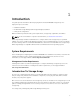
Figure 1. Example of Switch Zoning on SAN on an MD38xxf-series Fibre-Channel Storage Array World Wide Name Zoning There are several different switch zoning techniques used across various SANs. When configuring zoning with your storage array, using a 64 bit World Wide Name (WWN) to uniquely identify each component in your Fibre Channel switch fabric is recommended.
together, the switch allows the host server to see only devices included in that zone, decreasing the amount of time it would otherwise take for the host server to query attached, but out-of-zone, devices. Switch Zoning Guidelines The storage array imposes specific requirements that must be followed when setting up Fibre Channel switch zoning: • • • • • If a Fibre Channel switch is used to connect your host server and storage array, it must be zoned. Unzoned or open switches cannot be used.
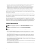
the host server(s) from losing access to data in the event of a path failure since both RAID controller modules can independently access all the physical disks in the storage array. SAN-Attached Cabling SAN-attached cabling configurations provide the highest level of redundancy and alternate-path connectivity between the host server and storage array. A SAN configuration using a Fibre Channel compatible switch fabric allows you to establish multiple redundant paths to data on the storage array.
Figure 2.
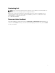
Switch Fabric A Switch Fabric B Server2_HBA_0 Server2_HBA_1 Array1_Ctrl-0-0 Array1_Ctrl-0-1 Array1_Ctrl-0-3 Array1_Ctrl-0-2 Array1_Ctrl-1-0 Array1_Ctrl-1-1 Array1_Ctrl-1-2 Array1_Ctrl-1-3 Zone3_Server3_HBA_0 Zone6_Server3_HBA_1 Server3_HBA_0 Server3_HBA_1 Array1_Ctrl-0-0 Array1_Ctrl-0-1 Array1_Ctrl-0-3 Array1_Ctrl-0-2 Array1_Ctrl-1-0 Array1_Ctrl-1-1 Array1_Ctrl-1-2 Array1_Ctrl-1-3 Remote Replication Cabling Example Remote Replication is a storage array premium feature that provides o
Figure 3.
Switch Fabric A Switch Fabric B Array1_Ctrl-0-0 Array1_Ctrl-0-1 Array1_Ctrl-1-0 Array1_Ctrl-0-2 Array1_Ctrl-1-2 Array1_Ctrl-1-1 Zone4_Server3_HBA_0_1 Zone9_Server3_HBA_0_0 Server3_HBA_0_1 Server3_HBA_0_0 Array2_Ctrl-0-1 Array2_Ctrl-0-0 Array2_Ctrl-0-2 Array2_Ctrl-1-0 Array2_Ctrl-1-1 Array2_Ctrl-1-2 Zone5_Server3_HBA_1_1 Zone10_Server3_HBA_1_0 Server3_HBA_1_1 Server3_HBA_1_0 Array2_Ctrl-0-1 Array2_Ctrl-0-0 Array2_Ctrl-0-2 Array2_Ctrl-1-0 Array2_Ctrl-1-1 Array2_Ctrl-1-2 Replication
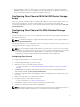
Figure 4. Mixed Environment Cabling PowerVault MD3060e Expansion Enclosures You can expand the capacity of your PowerVault MD3860f Series storage array by adding PowerVault MD3060e expansion enclosures. You can expand the physical disk drive pool to a maximum of 120 (or 180, if enabled using Premium Feature activation) physical disk drives using a maximum of two expansion enclosures. To connect the MD3060e expansion enclosure to your MD Series Dense RAID storage array, refer to the diagrams given here.
MD3060e Expansion cabling diagrams Figure 5.
Figure 6. Dual expansion diagram Expanding With New PowerVault MD3060e Expansion Enclosures NOTE: Hot plug of MD3060e expansion enclosure is not recommended. Power on all MD3060e expansion enclosures before you power on the array enclosure. For helpful videos and other resources on PowerVault MD series, see dell.com/PVresources. Perform the following steps to attach new PowerVault MD3060e expansion enclosures to a PowerVault MD3860f Series storage array: 1.
For more information, see the Support Matrix at dell.com/powervaultmanuals. 2. Install the software and driver package included on the PowerVault MD Series resource media. For information about installing the software, see Installing MD Storage Manager. 3. Using MD Storage Manager, update the RAID controller module firmware and NVSRAM to the latest versions available on dell.com/support. 4.
Installing MD Storage Manager 3 The PowerVault MD Series resource media contains software and drivers for both Linux and Microsoft Windows operating systems. The root of the media contains a readme.txt file describing changes to the software, updates, fixes, patches, and other important data applicable to both Linux and Windows operating systems. The readme.
The PowerVault MD Series resource media offers the following installation methods: • Graphical Installation (Recommended) — This is the recommended installation procedure. The installer presents a graphical wizard-driven interface that allows customization of components installed. • Console Installation — This installation procedure is useful for Linux users who do not desire to install an X-Window environment on their supported Linux platform.
8. Start MD Storage Manager and discover the array(s). NOTE: If Dynamic Host Configuration Protocol (DHCP) is not used on the network where the PowerVault MD storage array’s management ports are connected, it is recommended that you enable IPv6 on the management station to discover the storage array(s). NOTE: If automatic discovery does not find the new array, use the manual option and provide the default management ports IP addresses Controller 0 MGMT (port 0) : 192.168.128.
NOTE: On Red Hat Enterprise Linux 6 operating systems, run the following script from the root directory to install prerequisite packages: # md_prereq_install.sh 1. Copy the custom_silent.properties file in the /linux directory of the installation media or image to a writable location on the host server. 2. Modify the custom_silent.properties file to reflect the features, models and installation options to be used. Then, save the file. 3. After the custom_silent.
Post Installation Tasks 4 Before using the Dell PowerVault storage array for the first time, complete these initial configuration tasks in the order shown. These tasks are performed using the MD Storage Manager. 1. For out-of-band management, you must set the network configuration for each RAID controller module, including its Internet Protocol (IP) address, subnetwork mask (subnet mask), and gateway. NOTE: You can set the network configuration using a DHCP server. 2. 3. Launch MD Storage Manager.
• To add an array, in the EMW, select Automatic Discovery. NOTE: You can also add an array in the EMW using its known management ports IP addresses. Initial Setup Tasks 1. The name of the first storage array found is displayed in the Devices tab of the EMW. To see a list of all storage arrays found on the local network, expand Discovered Storage Arrays in the Devices tab of the EMW. 2. The default name for a newly installed PowerVault MD3860f series storage array is Unnamed.
Uninstalling MD Storage Manager 5 Uninstalling MD Storage Manager From Windows To uninstall the Modular Disk Storage Manager from Microsoft Windows Server: 1. Double-click Add or Remove Programs from the Control Panel. 2. Select Dell MD Storage Software from the list of programs. 3. Click Change/Remove. The Uninstall Complete window is displayed. 4. Follow the instructions on screen. 5. Select Yes to restart the system, and then click Done.
Uninstalling MD Storage Manager From Linux By default, PowerVault MD Storage Manager is installed in the /opt/dell/mdstoragemanager directory. If another directory was used during installation, navigate to that directory before beginning the uninstallation procedure. 1. From the installation directory, open the Uninstall Dell MD Storage Software directory. 2. Run the file Uninstall Dell MD Storage Software.exe. 3. From the Uninstall window, click Next, and follow the instructions on the screen.
Load Balancing 6 Load Balance Policy Multi-path drivers select the I/O path to a virtual disk through a specific RAID controller module. When the multi-path driver receives a new I/O to process, the driver tries to find a path to the current RAID controller module that owns the virtual disk. If the path to the current RAID controller module that owns the virtual disk cannot be found, the multi-path driver migrates the virtual disk ownership to the secondary RAID controller module.
If more than one data path to the virtual disk has the same weight value, the round robin with subset path selection policy is used to route I/O requests between the paths with the same weight value. The least path weight load balance policy is not supported on Linux operating systems. Setting Load Balance Policies in Linux Linux only supports round robin based load balancing. For more information, see Round Robin With Subset.
Appendix — Working With SFP Modules And Fiber Optic Cables 7 Each storage controller can have up to four FC host ports. A small-form-factor pluggable (SFP) module is used to connect a host port to a host or switch. The SFP module is inserted into the port, and then a fiber optic cable is inserted into the SFP module. The other end of the fiber optic cable is connected to an optical interface connector either in a FC HBA on a host or a switch. SFP modules are laser products.
5. Connect an FC cable. See Installing Fibre Channel Cables. Figure 7. Installing and Removing an SFP Module 1. FC IN slot (4) 2. SFP+ transceiver 3. fibre optic cable 4. gate Removing SFP Modules To remove SFP modules: 1. Remove the FC cable from the SFP module. See Removing Fibre Channel Cables. NOTE: To avoid damaging the cable or the SFP module, disconnect the FC cable before removing the SFP module. 2. Unlock the SFP module latch.
Installing Fibre Channel Cables WARNING: Data processing environments can contain equipment transmitting on system links with laser modules that operate at greater than Class 1 power levels. Never look into the end of an optical fiber cable or open receptacle. Before installing an FC cable, see Guidelines For Using Fibre Optic Cables. To install an FC cable: 1. If applicable, remove the protective cap from the SFP module and store the protective cap for future use. 2.
Appendix — Hardware Cabling Best Practices 8 Handling Static Sensitive Components Static electricity can damage memory modules, system boards, and other static-sensitive components. To prevent damaging the system, follow these precautions: • Move and store all components in the static-protective packaging. • Place components on a grounded surface before removing them from their static-protective packaging. • Grounded surfaces include static-dissipating mats or grounded workstations.
Labeling Cables Cabling is an important part of creating a robust storage array. Labeling the cables identifies system components and drive channels. System maintenance is easier when the cables are correctly identified. Label both ends of each cable. You can use adhesive office labels that are folded in half over the ends of each cable. Mark the labels with the port identifiers to which the cable is connected.