Dell PowerVault NX3300 Owner's Manual Regulatory Model: E16S Series Regulatory Type: E16S001
Notes, Cautions, and Warnings NOTE: A NOTE indicates important information that helps you make better use of your computer. CAUTION: A CAUTION indicates either potential damage to hardware or loss of data and tells you how to avoid the problem. WARNING: A WARNING indicates a potential for property damage, personal injury, or death. © 2012 Dell Inc.
Contents Notes, Cautions, and Warnings...................................................................................................2 1 About Your System......................................................................................................................9 Front Panel Features And Indicators........................................................................................................................9 LCD Panel Features...........................................................
Operating With A Setup Password Enabled....................................................................................................30 Entering The UEFI Boot Manager...........................................................................................................................30 Using The Boot Manager Navigation Keys......................................................................................................31 Boot Manager Screen....................................................
Expansion Cards And Expansion-Card Risers........................................................................................................52 Expansion Card Installation Guidelines............................................................................................................52 Removing An Expansion Card..........................................................................................................................53 Installing An Expansion Card....................................
VGA Module............................................................................................................................................................81 Removing The VGA Module.............................................................................................................................81 Installing The VGA Module...............................................................................................................................82 System Board.........................
Technical Specifications.......................................................................................................103 8 System Messages...................................................................................................................107 LCD Messages......................................................................................................................................................107 Viewing LCD Messages.........................................................
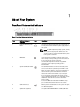
1 About Your System Front Panel Features And Indicators Figure 1. Front-Panel Features and Indicators Item Indicator, Button, or Connector 1 Power-on indicator, power button Icon Description The power-on indicator lights when the system power is on. The power button controls the power supply output to the system. NOTE: On ACPI-compliant operating systems, turning off the system using the power button causes the system to perform a graceful shutdown before power to the system is turned off.
Item Indicator, Button, or Connector Icon Description NOTE: DVD devices are data only. 6 vFlash media card slot Allows you to insert a vFlash media card. 7 LCD menu buttons Allows you to navigate the control panel LCD menu. 8 LCD panel Displays system ID, status information, and system error messages. The LCD lights blue during normal system operation. The LCD lights amber when the system needs attention, and the LCD panel displays an error code followed by descriptive text.
Item Button Description 1 Left Moves the cursor back in one-step increments. 2 Select Selects the menu item highlighted by the cursor. 3 Right Moves the cursor forward in one-step increments. During message scrolling: • • • • Press once to increase scrolling speed Press again to stop Press again to return to default scrolling speed Press again to repeat the cycle Home Screen The Home screen displays user-configurable information about the system.
View Menu NOTE: When you select an option in the View menu, you must confirm the option before proceeding to the next action. Option Description iDRAC IP Displays the IPv4 or IPv6 addresses for the iDRAC7. Addresses include DNS (Primary and Secondary), Gateway, IP, and Subnet (IPv6 does not have Subnet). MAC Displays the MAC addresses for iDRAC, iSCSI, or Network devices.
Memory indicator Condition Corrective Action The indicator blinks amber if a memory error occurs. See the system event log or system messages for the location of the failed memory. Reinstall the memory device. If the problem persists, see Getting Help. Hard-Drive Indicator Patterns Figure 3. Hard-Drive Indicators 1. hard-drive activity indicator (green) 2.
Back-Panel Features And Indicators Figure 4. Back-Panel Features and Indicators Item Indicator, Button, or Connector 1 System identification button Icon Description The identification buttons on the front and back panels can be used to locate a particular system within a rack. When one of these buttons is pressed, the LCD panel on the front and the system status indicator on the back blink until one of the buttons is pressed again. Press to toggle the system ID on and off.
Item Indicator, Button, or Connector Icon 10 Power supply (PSU1) 11 Power supply (PSU2) Description AC 495 W, 750 W, or 1100 W Or DC 1100 W (when available) NIC Indicator Codes Figure 5. NIC Indicator 1. link indicator 2. activity indicator Indicator Indicator Code Link and activity indicators are off The NIC is not connected to the network. Link indicator is green The NIC is connected to a valid network at its maximum port speed (1 Gbps or 10 Gbps).
1. AC power supply status indicator/handle Figure 7. DC Power Supply Status Indicator 1. DC power supply status indicator Power Indicator Pattern Condition Not lit Power is not connected. Green The handle/LED indicator lights green indicating that a valid power source is connected to the power supply and that the power supply is operational. Flashing amber Indicates a problem with the power supply.
Other Information You May Need WARNING: See the safety and regulatory information that shipped with your system. Warranty information may be included within this document or as a separate document. • The Getting Started Guide provides an overview of setting up your system, and technical specifications. This document is available online at support.dell.com/manuals. • The rack documentation included with your rack solution describes how to install your system into a rack, if required.
Using The System Setup And Boot Manager 2 System Setup enables you to manage your system hardware and specify BIOS-level options. The following keystrokes provide access to system features during startup: Keystroke Description Enters the System Setup. Enters System Services, which opens the Dell Lifecycle Controller 2 (LC2).
mode. Thereafter, you must boot the system in the same boot mode (BIOS or UEFI) to access the installed operating system. Trying to boot the operating system from the other boot mode will cause the system to halt at startup. NOTE: Operating systems must be UEFI-compatible to be installed from the UEFI boot mode. DOS and 32-bit operating systems do not support UEFI and can only be installed from the BIOS boot mode. NOTE: For the latest information on supported operating systems, go to dell.com/ossupport.
System Setup Main Screen NOTE: Press to reset the BIOS or UEFI settings to their default settings. Menu Item Description System BIOS This option is used to view and configure BIOS settings. iDRAC Settings This option is used to view and configure iDRAC settings. Device Settings This option is used to view and configure device settings. System BIOS Screen NOTE: The options for System Setup change based on the system configuration.
Menu Item Description System Service Tag Displays the system Service Tag. System Manufacturer Displays the name of system manufacturer. System Manufacturer Contact Information Displays the contact information of the system manufacturer. Memory Settings Screen Menu Item Description System Memory Size Displays the amount of memory installed in the system. System Memory Type Displays the type of memory installed in the system. System Memory Speed Displays the system memory speed.
Menu Item Description Alternate RTID (Requestor Transaction ID) Setting Allows you to allocate more RTIDs to the remote socket increasing cache performance between the sockets or work in normal mode for NUMA. By default, the Alternate RTID (Requestor Transaction ID) Setting is set to Disabled. Virtualization Technology Allows you to enable or disable the additional hardware capabilities provided for virtualization. By default, the Virtualization Technology option is set to Enabled.
Menu Item Description Port E Auto enables BIOS support for the device attached to SATA port E. Off disables BIOS support for the device. By default, Port E is set to Auto. Port F Auto enables BIOS support for the device attached to SATA port F. Off disables BIOS support for the device. By default, Port F is set to Auto. Boot Settings Screen Menu Item Description Boot Mode Allows you to set the boot mode of the system.
Menu Item Description NOTE: This option is displayed only if IDSDM is installed on the system board. Internal SD Card Redundancy If set to Mirror mode, data is written on both SD cards. If any one of the SD card fails, data is written to the active SD card. Data from this card is copied to the replacement SD card at the next boot. By default, Internal SD Card Redundancy option is set to Mirror. NOTE: This option is displayed only if IDSDM is installed on the system board.
Menu Item Description Remote Terminal Type Allows you to set the remote console terminal type. By default, the Remote Terminal Type option is set to VT 100/VT 220. Redirection After Boot Allows you to enable or disable to the BIOS console redirection when the operating system is loaded. By default, the Redirection After Boot option is set to Enabled. System Profile Settings Screen Menu Item Description System Profile Allows you to set the system profile.
System Security Screen Menu Item Description Intel AES-NI The Intel AES-NI option improves the speed of applications by performing encryption and decryption using the Advanced Encryption Standard Instruction Set and is set to Enabled by default. System Password Allows you to set the system password. This option is set to Enabled by default and is read-only if the password jumper is not installed in the system. Setup Password Allows you to set the setup password.
Miscellaneous Settings Menu Item Description System Time Allows you to set the time on the system. System Date Allows you to set the date on the system. Asset Tag Displays the asset tag and allows you to modify it for security and tracking purposes. Keyboard NumLock Allows you to set whether the system boots with the NumLock enabled or disabled. By default the Keyboard NumLock is set to On. NOTE: This field does not apply to 84-key keyboards.
1. To enter System Setup, press immediately after a power-on or reboot. 2. In the System Setup Main Menu, select System BIOS and press . The System BIOS screen is displayed. 3. In the System BIOS screen, select System Security and press . The System Security screen is displayed. 4. In the System Security screen, verify that Password Status is Unlocked. 5. Select System Password , enter your system password, and press or .
Using Your System Password To Secure Your System NOTE: If you have assigned a setup password, the system accepts your setup password as an alternate system password. 1. Turn on or reboot your system. 2. Type your password and press . When Password Status is Locked, type the password and press when prompted at reboot. If an incorrect system password is entered, the system displays a message and prompts you to re-enter your password. You have three attempts to enter the correct password.
If your operating system begins to load before you press , allow the system to finish booting, and then restart your system and try again. Using The Boot Manager Navigation Keys Key Description Up arrow Moves to the previous field. Down arrow Moves to the next field. Allows you to type in a value in the selected field (if applicable) or follow the link in the field. Spacebar Expands or collapses a drop-down list, if applicable. Moves to the next focus area.
UEFI Boot Menu Menu Item Description Select UEFI Boot Option Displays the list of available UEFI boot options (marked with asterisks), select the boot option you wish to use and press . Add Boot Option Adds a new boot option. Delete Boot Option Deletes an existing boot option. Boot From File Sets a one-time boot option not included in the boot option list. Embedded System Management The Dell Lifecycle Controller provides advanced embedded systems management throughout the server’s lifecycle.
Installing System Components 3 Recommended Tools You may need the following items to perform the procedures in this section: • Key to the system keylock • #1 and #2 Phillips screwdrivers • T10 and T15 Torx screwdrivers • Wrist grounding strap connected to ground Following tools are required for assembling cables for a DC power supply unit (PSU), when available: • Wire-stripper pliers capable of removing insulation from size 10 AWG solid or stranded, insulated copper wire • AMP 90871-1 hand-crim
1. 2. 3. 4. release latch keylock front bezel locking hook Installing The Front Bezel 1. Hook the right end of the bezel onto the chassis. 2. Fit the free end of the bezel onto the system. 3. Secure the bezel with the keylock. Opening And Closing The System WARNING: Whenever you need to lift the system, get others to assist you. To avoid injury, do not attempt to lift the system by yourself.
Figure 9. Opening and Closing the System 1. system cover 2. latch 3. latch release lock Closing The System 1. Lift the latch on the cover. 2. Place the cover onto the chassis and offset the cover slightly back so that it clears the chassis hooks and lays flush on the chassis. 3. Push down the latch to move the cover into the closed position. 4. Rotate the latch release lock in a clockwise direction to secure the cover. 5.
Figure 10. Inside the System 1. 2. 3. 4. 5. 6. 7. 8. 9. 10. control panel assembly cable securing clip cooling fans (7) cable securing bracket cooling shroud power supplies (2) chassis intrusion switch riser card 3 network daughter card riser card 2 11. 12. 13. 14. 15. 16. 17. 18.
Figure 11. Removing and Installing the Cooling Shroud 1. cooling shroud Installing The Cooling Shroud CAUTION: Many repairs may only be done by a certified service technician. You should only perform troubleshooting and simple repairs as authorized in your product documentation, or as directed by the online or telephone service and support team. Damage due to servicing that is not authorized by Dell is not covered by your warranty. Read and follow the safety instructions that came with the product.
The system contains 24 memory sockets split into two sets of 12 sockets, one set per processor. Each 12-socket set is organized into four channels. In each channel, the release levers of the first socket are marked white, the second socket black, and the third socket green. NOTE: DIMMs in sockets A1 to A12 are assigned to processor 1 and DIMMs in sockets B1 to B12 are assigned to processor 2. Figure 12.
Processor 2 channel 0: slots B1, B5, and B9 channel 1: slots B2, B6, and B10 channel 2: slots B3, B7, and B11 channel 3: slots B4, B8, and B12 The following table shows the memory populations and operating frequencies for the supported configurations. DIMM Type DIMMs Populated/ Channel Operating Frequency (in MT/s) 1.5 V Maximum DIMM Rank/ Channel 1.
• Memory modules of different sizes can be mixed provided that other memory population rules are followed (for example, 2 GB and 4 GB memory modules can be mixed). • Populate four DIMMs per processor (one DIMM per channel) at a time to maximize performance. • If memory modules with different speeds are installed, they will operate at the speed of the slowest installed memory module(s) or slower depending on system DIMM configuration.
• Memory modules must be identical in size, speed, and technology. • DIMMs installed in memory sockets with white release tabs must be identical and similar rule applies for sockets with black and green release tabs. This ensures that identical DIMMs are installed in matched pairs for example, A1 with A2, A3 with A4, A5 with A6, and so on.
System Capacity DIMM Size (in Number of (in GB) GB) DIMMs DIMM Rank, Organization, and Frequency DIMM Slot Population NOTE: 16 GB DIMMs must be installed in slots numbered A1, A2, A3, A4, A5, A6, A7, and A8 and 8 GB DIMMs must be installed in slots A9 and A11. 384 32 12 LRDIMM, x4, 1333 MT/s A1, A2, A3, A4, A5, A6, A7, A8, A9, A10, A11, A12 Table 2.
System Capacity (in GB) DIMM Size (in GB) Number of DIMMs DIMM Rank, Organization, and Frequency DIMM Slot Population NOTE: 16 GB DIMMs must be installed in slots numbered A1, A2, A3, A4, B1, B2, B3, and B4 and 8 GB DIMMs must be installed in slots A5, A6, B5, and B6.
CAUTION: Handle each memory module only on either card edge, making sure not to touch the middle of the memory module. 5. Press down and out on the ejectors on each end of the socket until the memory module pops out of the socket. Figure 13. Removing and Installing a Memory Module 1. memory module 2. memory-module socket ejectors (2) 3. alignment key 6. Install memory-module blanks in vacant memory-module socket(s) to ensure proper system cooling. 7. Install the cooling shroud. 8. Close the system.
4. Locate the memory-module sockets. 5. Press the ejectors on the memory module socket down and out to allow the memory module to be inserted into the socket. If a memory module blank is installed in the socket, remove it. NOTE: Retain removed memory-module blank(s) for future use. CAUTION: Handle each memory module only on either card edge, making sure not to touch the middle of the memory module. 6.
Figure 14. Removing and Installing a 2.5 Inch Hard-Drive Blank 1. hard-drive blank 2. release button Installing A 2.5 Inch Hard-Drive Blank 1. If installed, remove the front bezel. 2. Insert the hard-drive blank into the hard-drive slot until the release button clicks into place. 3. If applicable, install the front bezel. Removing A Hot-Swap Hard Drive CAUTION: To prevent data loss, ensure that your operating system supports hot-swap drive installation.
Figure 15. Removing and Installing a Hot-Swap Hard Drive 1. release button 2. hard drive 3. hard-drive carrier handle Installing A Hot-Swap Hard Drive CAUTION: Many repairs may only be done by a certified service technician. You should only perform troubleshooting and simple repairs as authorized in your product documentation, or as directed by the online or telephone service and support team. Damage due to servicing that is not authorized by Dell is not covered by your warranty.
Removing A Hard Drive From A Hard-Drive Carrier 1. Remove the screws from the slide rails on the hard-drive carrier. 2. Lift the hard drive out of the hard-drive carrier. Figure 16. Removing and Installing a Hard Drive Into a Hard-Drive Carrier 1. hard-drive carrier 2. hard drive 3. screws (4) Installing A Hard Drive Into A Hard-Drive Carrier CAUTION: Many repairs may only be done by a certified service technician.
Optical Drive Removing The Optical Drive CAUTION: Many repairs may only be done by a certified service technician. You should only perform troubleshooting and simple repairs as authorized in your product documentation, or as directed by the online or telephone service and support team. Damage due to servicing that is not authorized by Dell is not covered by your warranty. Read and follow the safety instructions that came with the product. NOTE: This procedure applies only to the 8-hard drive system. 1.
3. release tab Installing The Optical Drive CAUTION: Many repairs may only be done by a certified service technician. You should only perform troubleshooting and simple repairs as authorized in your product documentation, or as directed by the online or telephone service and support team. Damage due to servicing that is not authorized by Dell is not covered by your warranty. Read and follow the safety instructions that came with the product. NOTE: This procedure applies only to the 8-hard drive system. 1.
Figure 18. Removing and Installing a Cooling Fan 1. cooling fan assembly 2. cooling fans (7) 3. cooling fan connectors (7) Installing A Cooling Fan CAUTION: Many repairs may only be done by a certified service technician. You should only perform troubleshooting and simple repairs as authorized in your product documentation, or as directed by the online or telephone service and support team. Damage due to servicing that is not authorized by Dell is not covered by your warranty.
Replacing The Internal USB Key CAUTION: Many repairs may only be done by a certified service technician. You should only perform troubleshooting and simple repairs as authorized in your product documentation, or as directed by the online or telephone service and support team. Damage due to servicing that is not authorized by Dell is not covered by your warranty. Read and follow the safety instructions that came with the product. 1.
Table 3. Supported Expansion Cards Riser PCIe Slot Processor Connection Height Length Link Width Slot Width 2 1 Processor 1 Low Profile Half Length x8 x16 Processor 2 Low Profile Half Length x16 x16 Processor 1 Full height Three-fourth Length x16 x16 3 2 CAUTION: If the 10 GbE network daughter card is installed, you cannot install the GPU card. NOTE: Only a three-fourth length GPU card is supported for the PCIe expansion card slot (slot 2) on riser 3.
NOTE: You must install a filler bracket over an empty expansion slot to maintain Federal Communications Commission (FCC) certification of the system. The brackets also keep dust and dirt out of the system and aid in proper cooling and airflow inside the system. 7. Close the system. 8. Reconnect the system to its electrical outlet and turn the system on, including any attached peripherals. Figure 20. Removing and Installing the Expansion Card 1. expansion card 2. expansion-card connector 3.
NOTE: When installing a GPU card on riser 3, connect the GPU card power cable to the power connector on riser 3. 10. Close the system. 11. Reconnect the system to its electrical outlet and turn the system on, including any attached peripherals. 12. Install any device drivers required for the card as described in the documentation for the card. Removing Expansion-Card Risers CAUTION: Many repairs may only be done by a certified service technician.
5. connector Figure 22. Removing and Installing the Expansion Card Riser 3 1. connector 2. expansion card riser 3 4. If applicable, remove or install an expansion card on the riser. 5. Replace the expansion-card riser. 6. Close the system. 7. Reconnect the system to its electrical outlet and turn the system on, including any attached peripherals. Installing Expansion-Card Risers CAUTION: Many repairs may only be done by a certified service technician.
Replacing An SD vFlash Card NOTE: This procedure applies only to the 8-hard drive system. 1. Locate the vFlash media slot on the system. 2. To remove the installed SD vFlash card, push inward on the card to release it. 3. Pull the card from the card slot. Figure 23. Removing and Installing the SD vFlash Card 1. SD vFlash card 2. SD vFlash card slot 4. To install the SD vFlash card, with the label side facing up, insert the contact-pin end of the SD card into the card slot on the module.
6. Close the system. 7. Reconnect the system to its electrical outlet and turn the system on, including any attached peripherals. Figure 24. Removing and Installing the Internal Dual SD Module 1. 2. 3. 4. 5. blue pull tab SD card 1 SD card 2 dual SD module connector on the system board Installing The Internal Dual SD Module CAUTION: Many repairs may only be done by a certified service technician.
6. Close the system. 7. Reconnect the system to its electrical outlet and turn the system on, including any attached peripherals. Internal SD Card Removing An Internal SD Card CAUTION: Many repairs may only be done by a certified service technician. You should only perform troubleshooting and simple repairs as authorized in your product documentation, or as directed by the online or telephone service and support team.
Removing The Integrated Storage Controller CAUTION: Many repairs may only be done by a certified service technician. You should only perform troubleshooting and simple repairs as authorized in your product documentation, or as directed by the online or telephone service and support team. Damage due to servicing that is not authorized by Dell is not covered by your warranty. Read and follow the safety instructions that came with the product. 1.
Installing The Integrated Storage Controller CAUTION: Many repairs may only be done by a certified service technician. You should only perform troubleshooting and simple repairs as authorized in your product documentation, or as directed by the online or telephone service and support team. Damage due to servicing that is not authorized by Dell is not covered by your warranty. Read and follow the safety instructions that came with the product. 1.
Figure 25. Removing and Installing the Network Daughter Card 1. 2. 3. 4. captive screw sockets (2) connector on the system board captive screws (2) touch point 5. network daughter card 6. back panel slots for RJ-45 connectors Installing The Network Daughter Card CAUTION: Many repairs may only be done by a certified service technician. You should only perform troubleshooting and simple repairs as authorized in your product documentation, or as directed by the online or telephone service and support team.
• Installing an additional processor • Replacing a processor NOTE: To ensure proper system cooling, you must install a processor blank and a heat-sink blank in any empty processor socket. Removing A Processor CAUTION: Many repairs may only be done by a certified service technician. You should only perform troubleshooting and simple repairs as authorized in your product documentation, or as directed by the online or telephone service and support team.
Figure 26. Removing and Installing the Heat Sink 1. 2. 3. 4. heat sink retention sockets (2) retention screws (2) processor CAUTION: The processor is held in its socket under strong pressure. Be aware that the release lever can spring up suddenly if not firmly grasped. 8. 9. 64 Position your thumb firmly over the processor socket-release lever near the unlock icon from the locked position by pushing down and out from under the tab.
Figure 27. Processor Shield Opening and Closing Lever Sequence 1. 2. 3. 4. 5. close-lock symbol processor socket-release lever processor processor socket-release lever open-lock symbol 10. Rotate the processor shield upward and out of the way. CAUTION: The socket pins are fragile and can be permanently damaged. Be careful not to bend the pins in the socket when removing the processor out of the socket. 11.
Figure 28. Removing and Installing a Processor 1. 2. 3. 4. 5. processor socket-release lever pin 1 indicator processor socket-release lever processor shield processor 6. ZIF socket 7. socket keys (4) 8. notches in processor (4) NOTE: After removing the processor, place it in an antistatic container for reuse, return, or temporary storage. Do not touch the bottom of the processor. Touch only the side edges of the processor.
3. Open the system. 4. Remove the cooling shroud. WARNING: The heat sink and processor are hot to the touch for some time after the system has been powered down. Allow the heat sink and processor to cool before handling them. CAUTION: Never remove the heat sink from a processor unless you intend to remove the processor. The heat sink is necessary to maintain proper thermal conditions. 5. Remove the heat sink/heat-sink blank and processor/processor blank, as applicable.
When only one power supply is installed, the power supply configuration is non-redundant (1 + 0). Power is supplied to the system only by the single power supply. NOTE: If two power supplies are used, they must be of the same type and have the same maximum output power. CAUTION: When installing 1100 W AC or DC PSU, you must install both the PSUs. Your system does not support only one 1100 W AC or DC PSU.
Figure 29. Removing and Installing an AC Power Supply 1. 2. 3. 4. connector power supply release latch power supply handle Installing An AC Power Supply CAUTION: Many repairs may only be done by a certified service technician. You should only perform troubleshooting and simple repairs as authorized in your product documentation, or as directed by the online or telephone service and support team. Damage due to servicing that is not authorized by Dell is not covered by your warranty.
Wiring Instructions For A DC Power Supply Your system supports up to two –(48–60) V DC power supplies (when available). WARNING: For equipment using –(48–60) V DC power supplies, a qualified electrician must perform all connections to DC power and to safety grounds. Do not attempt connecting to DC power or installing grounds yourself. All electrical wiring must comply with applicable local or national codes and practices.
3. Connect the safety ground wire to the grounding post on the back of the system using a #6-32 nut equipped with a locking washer. Figure 30. Assembling and Connecting the Safety Ground Wire 1. 2. 3. 4. 5. safety ground wire grounding post locking washer spring washer #6-32 nut Assembling The DC Input Power Wires WARNING: For equipment using –(48–60) V DC power supplies, a qualified electrician must perform all connections to DC power and to safety grounds.
Figure 31. Assembling the DC Input Power Wires 1. 2. 3. 4. DC power socket rubber cap captive screws (2) DC power connector 5. wire –48 V 6. wire RTN 7. grounding wire Removing A DC Power Supply WARNING: For equipment using –(48–60) V DC power supplies, a qualified electrician must perform all connections to DC power and to safety grounds. Do not attempt connecting to DC power or installing grounds yourself. All electrical wiring must comply with applicable local or national codes and practices.
Figure 32. Removing and Installing a DC Power Supply 1. 2. 3. 4. 5. connector power supply power supply status indicator release latch power supply handle Installing A DC Power Supply WARNING: For equipment using –(48–60) V DC power supplies, a qualified electrician must perform all connections to DC power and to safety grounds. Do not attempt connecting to DC power or installing grounds yourself. All electrical wiring must comply with applicable local or national codes and practices.
Removing The Power Supply Blank CAUTION: To ensure proper system cooling, the power supply blank must be installed in the second power supply bay in a non-redundant configuration. Remove the power supply blank only if you are installing a second power supply. If you are installing a second power supply, remove the power supply blank in the bay by pulling outward on the blank. Figure 33. Removing and Installing the Power Supply Blank 1.
1. Turn off the system, including any attached peripherals, and disconnect the system from the electrical outlet and peripherals. 2. Open the system. 3. Press the touch points and lift the system battery cover up and away from the network daughter card cooling shroud. Figure 34. Removing the System Battery Cover 1. system battery cover 2. network daughter card cooling shroud 3. touch points 4. Locate the battery socket.
6. To install a new system battery, hold the battery with the "+" facing up and slide it under the securing tabs at the positive side of the connector. 7. Press the battery straight down into the connector until it snaps into place. 8. Align the back of the system battery cover with the notch on the network daughter card cooling shroud and push the system battery cover down into the notches till it snaps into place. 9. Close the system. 10.
Figure 36. Removing and Installing the 2.5 Inch (x4) Hard-Drive Backplane 1. 2. 3. 4. 5. hard-drive backplane backplane signal cable backplane power cable release tab SAS A cable Figure 37. Cabling Diagram—2.
1. 2. 3. 4. 5. cable retention bracket system board integrated storage controller card SAS connector on system board SAS backplane Installing The Hard-Drive Backplane CAUTION: Many repairs may only be done by a certified service technician. You should only perform troubleshooting and simple repairs as authorized in your product documentation, or as directed by the online or telephone service and support team. Damage due to servicing that is not authorized by Dell is not covered by your warranty.
Figure 38. Removing and Installing the Control Panel Board 1. 2. 3. 4. control panel board screws (2) control-panel cable display module cable Installing The Control Panel Board CAUTION: Many repairs may only be done by a certified service technician. You should only perform troubleshooting and simple repairs as authorized in your product documentation, or as directed by the online or telephone service and support team.
1. If installed, remove the front bezel. 2. Turn off the system, including any attached peripherals, and disconnect the system from the electrical outlet and peripherals. 3. Open the system. CAUTION: The display module connector is a ZIF (zero insertion force) connector. Ensure that the locking tab on the connector is released before removal and insertion. The locking tab must be engaged after insertion. 4. Disconnect the display module cable from the control panel board. 5.
Installing the Control Panel CAUTION: Many repairs may only be done by a certified service technician. You should only perform troubleshooting and simple repairs as authorized in your product documentation, or as directed by the online or telephone service and support team. Damage due to servicing that is not authorized by Dell is not covered by your warranty. Read and follow the safety instructions that came with the product. 1.
Figure 40. Removing and Installing the VGA Module 1. 2. 3. 4. control panel display module cable screw (top) VGA module cable 5. screw (bottom) 6. VGA module Installing The VGA Module NOTE: This procedure applies only to the 8-hard drive system. CAUTION: Many repairs may only be done by a certified service technician. You should only perform troubleshooting and simple repairs as authorized in your product documentation, or as directed by the online or telephone service and support team.
System Board Removing The System Board CAUTION: Many repairs may only be done by a certified service technician. You should only perform troubleshooting and simple repairs as authorized in your product documentation, or as directed by the online or telephone service and support team. Damage due to servicing that is not authorized by Dell is not covered by your warranty. Read and follow the safety instructions that came with the product.
a. mini SAS cable connector b. metal tab 6. c. connector on the system board Disconnect all other cables from the system board. CAUTION: Take care not to damage the system identification button while removing the system board from the chassis. 7. Grasp the system-board holder, lift the blue release pin, slide the system board toward the front of the system, and lift the system board out of the chassis.
Installing The System Board CAUTION: Many repairs may only be done by a certified service technician. You should only perform troubleshooting and simple repairs as authorized in your product documentation, or as directed by the online or telephone service and support team. Damage due to servicing that is not authorized by Dell is not covered by your warranty. Read and follow the safety instructions that came with the product. 1. Unpack the new system board assembly.
Troubleshooting Your System 4 Safety First—For You And Your System CAUTION: Many repairs may only be done by a certified service technician. You should only perform troubleshooting and simple repairs as authorized in your product documentation, or as directed by the online or telephone service and support team. Damage due to servicing that is not authorized by Dell is not covered by your warranty. Read and follow the safety instructions that came with the product.
7. Power down all attached USB devices and disconnect them from the system. 8. Restart the system and, if your keyboard is functioning, enter the System Setup. Verify that all USB ports are enabled on the Integrated Devices screen, in the System Setup options. If your keyboard is not functioning, you can also use remote access. If the system is not accessible, reset the NVRAM_CLR jumper inside your system and restore the BIOS to the default settings. 9.
3. Disassemble components from the system: – Hard drives – Hard-drive backplane – USB memory key – Cooling shroud – Expansion-card risers (if present) – Expansion cards – Power supply(s) – Cooling-fan assembly (if present) – Cooling fans – Processor(s) and heat sink(s) 4. – Memory modules Let the system dry thoroughly for at least 24 hours. 5. Reinstall the components you removed in step 3. 6. Close the system. 7. Turn on the system and attached peripherals.
If the tests fail, see Getting Help. Troubleshooting The System Battery CAUTION: Many repairs may only be done by a certified service technician. You should only perform troubleshooting and simple repairs as authorized in your product documentation, or as directed by the online or telephone service and support team. Damage due to servicing that is not authorized by Dell is not covered by your warranty. Read and follow the safety instructions that came with the product.
Troubleshooting Cooling Fans CAUTION: Many repairs may only be done by a certified service technician. You should only perform troubleshooting and simple repairs as authorized in your product documentation, or as directed by the online or telephone service and support team. Damage due to servicing that is not authorized by Dell is not covered by your warranty. Read and follow the safety instructions that came with the product. 1. Open the system. 2. Reseat the fan or the fan's power cable. 3.
15. As the system boots, observe any error message that is displayed and the diagnostic indicators on the front of the system. 16. If the memory problem is still indicated, repeat step 12 through step 15 for each memory module installed. If the problem persists after all memory modules have been checked, see Getting Help. Troubleshooting An Internal USB Key CAUTION: Many repairs may only be done by a certified service technician.
9. Reconnect the system to its electrical outlet and turn the system on, including any attached peripherals. 10. Enter the System Setup and ensure that the Internal SD Card Port and Internal SD Card Redundancy mode is enabled. 11. Check if the SD card is functioning properly. If the problem persists, see Getting Help. Troubleshooting An Optical Drive CAUTION: Many repairs may only be done by a certified service technician.
Troubleshooting A Hard Drive CAUTION: Many repairs may only be done by a certified service technician. You should only perform troubleshooting and simple repairs as authorized in your product documentation, or as directed by the online or telephone service and support team. Damage due to servicing that is not authorized by Dell is not covered by your warranty. Read and follow the safety instructions that came with the product. CAUTION: This troubleshooting procedure can erase data stored on the hard drive.
12. Reconnect the system to the electrical outlet, and turn on the system and attached peripherals. 13. Run the appropriate diagnostic test. For more information, see Using System Diagnostics. If the tests fail, see Getting Help. 14. For each expansion card you removed in step 10, perform the following steps: a. Turn off the system and attached peripherals, and disconnect the system from the electrical outlet. b. Open the system. c. Reinstall one of the expansion cards. d. Close the system. e.
Troubleshooting Processors CAUTION: Many repairs may only be done by a certified service technician. You should only perform troubleshooting and simple repairs as authorized in your product documentation, or as directed by the online or telephone service and support team. Damage due to servicing that is not authorized by Dell is not covered by your warranty. Read and follow the safety instructions that came with the product. 1. Run the appropriate diagnostics test.
Using System Diagnostics 5 If you experience a problem with your system, run the system diagnostics before contacting Dell for technical assistance. The purpose of running system diagnostics is to test your system hardware without requiring additional equipment or risking data loss. If you are unable to fix the problem yourself, service and support personnel can use the diagnostics results to help you solve the problem.
The ePSA Pre-boot System Assessment window is displayed, listing all devices detected in the system. The diagnostics starts executing the tests on all the detected devices. System Diagnostic Controls Menu Description Configuration Displays the configuration and status information of all detected devices. Results Displays the results of all tests that are executed. System Health Provides the current overview of the system performance.
Jumpers And Connectors 6 System Board Jumper Settings For information on resetting the password jumper to disable a password, see Disabling A Forgotten Password. Table 5. System Board Jumper Settings Jumper PWRD_EN Setting (default) Description The password feature is enabled (pins 4–6). The password feature is disabled (pins 2–4). iDRAC local access is unlocked at the next AC power cycle. NVRAM_CLR (default) The configuration settings are retained at system boot (pins 1–3).
System Board Connectors Figure 42.
Item Connector Description 11 J_VIDEO_REAR Video connector 12 J_COM1 Serial connector 13 J_IDRAC_RJ45 iDRAC7 connector 14 J_CYC System identification connector 15 CYC_ID System identification button 16 J_RISER_2A Riser 2 connector 17 J_RISER_1A Riser 1 connector 18 TOUCH POINT Touch point for holding system board 19 J_RISER_2B Riser 2 connector 20 J_RISER_1B Riser 1 connector 21 J_STORAGE Storage controller card connector 22 J_SASX8 SATA connector 23 J_USB_INT Intern
Disabling A Forgotten Password The system's software security features include a system password and a setup password. The password jumper enables these password features or disables them and clears any password(s) currently in use. CAUTION: Many repairs may only be done by a certified service technician. You should only perform troubleshooting and simple repairs as authorized in your product documentation, or as directed by the online or telephone service and support team.
7 Technical Specifications Processor Processor type One or two Intel Xeon processor E5-2600 product family Expansion Bus Bus type PCI Express Generation 3 Expansion slots using riser card: Riser 1 (Slot 1) One half-height, half-length x8 link (Slot 2) One half-height, half-length x16 link Riser 2 (Slot 1) One half-height, half-length x8 link or one halfheight, half-length x16 link NOTE: Both processors must be installed to use the slots on riser 1 and the x16 link on riser 2.
Memory UDIMM Up to 128 GB Drives Hard drives Up to four 2.5 inch, internal, hot-swappable SAS, SATA, or Nearline SAS hard drives NOTE: Four–hard-drive systems support software RAID. For more information on software RAID, see the Dell PowerEdge RAID Controller (PERC) documentation at support.dell.com/manuals. Optical drive One optional SATA DVD-ROM drive or DVD+/-RW drive NOTE: DVD devices are data only.
Environmental NOTE: For additional information about environmental measurements for specific system configurations, see dell.com/environmental_datasheets. Standard Operating Temperature Continuous operation: 10 °C to 35 °C at 10% to 80% relative humidity (RH), with 26 °C max dew point. De-rate maximum allowable dry bulb temperature at 1 °C per 300 m above 900 m (1 °F per 550 ft). Storage Temperature –40 °C to 65 °C (–40 °F to 149 °F) with a maximum temperature gradation of 20 °C per hour.
System Messages 8 LCD Messages NOTE: Applicable only if your system has an LCD display. The LCD messages consist of brief text messages that refer to events recorded in the System Event Log (SEL). For information on the SEL and configuring system management settings, see the systems management software documentation. NOTE: If your system fails to boot, press the System ID button for at least 5 seconds until an error code is displayed on the LCD. Record the code, then see System Error Messages.
Error Code Message Information AMP0302 Message The system board current is greater than the upper warning threshold. Details System board current is outside of the optimum range. Action 1. Review system power policy. 2. Check system logs for power related failures. 3. Review system configuration changes. 4. If the issue persists, see Getting Help. AMP0303 Message The system board current is greater than the upper critical threshold.
Error Code Message Information BAT0002 BAT0017 CPU0000 CPU0001 CPU0005 CPU0010 CPU0023 Message The system board battery has failed. LCD Message The system board battery has failed. Check battery. Details The system board battery is either missing or bad. Action See Getting Help. Message The battery has failed. LCD Message The battery has failed. Check battery. Details The battery is either missing, bad, or unable to charge due to thermal issues.
Error Code Message Information CPU0204 Message CPU voltage is outside of range. LCD Message CPU voltage is outside of range. Re-seat CPU. Details Voltages outside the allowable range may damage electrical components or may cause the system to shutdown. Action 1. Turn off the system and remove input power for one minute. 2. Ensure the processor is seated correctly. 3. Reapply input power and turn on the system. 4. If the issue persists, see Getting Help.
Error Code Message Information 4. Reapply input power and turn on the system. 5. If the issue persists, see Getting Help. CPU0703 Message CPU bus initialization error detected. LCD Message CPU bus initialization error detected. Power cycle system. Details System event log and operating system logs may indicate that the exception is external to the processor. Action 1. Check system and operating system logs for exceptions. If no exceptions are found, continue. 2.
Error Code Message Information HWC1001 HWC2003 HWC2005 MEM0000 MEM0001 MEM0007 112 Details Fan has failed. Action Remove and reinstall failed fans or install additional fans. Message The is absent. LCD Message The is absent. Check hardware. Details The absent device may be necessary for proper operation. System functionality may be degraded. Action Reinstall or reconnect the hardware. Message The storage cable is not connected, or is improperly connected.
Error Code Message Information Action MEM0701 MEM0702 MEM1205 MEM1208 MEM8000 PCI1302 PCI1304 Check the memory configuration. Re-seat the memory modules. If the issue persists, see Getting Help. Message Correctable memory error rate exceeded for . Details The memory may not be operational. This an early indicator of a possible future uncorrectable error. Action Re-seat the memory modules. If the issue persists, see Getting Help.
Error Code Message Information PCI1308 PCI1320 PCI1342 PCI1348 PCI1360 PDR0001 114 Action Cycle input power, update component drivers, if device is removable, reinstall the device. Message A PCI parity error was detected on a component at bus devicefunction . LCD Message PCI parity error on bus device function . Power cycle system. Details System performance may be degraded, PCI device may fail to operate, or system may fail to operate.
Error Code Message Information Action PDR1016 PST0128 PST0129 PSU0001 PSU0002 PSU0003 PSU0006 Remove and re-seat the failed disk. If the issue persists, see Getting Help. Message Drive is removed from disk drive bay . LCD Message Drive removed from disk drive bay . Check drive. Details The controller detected that the drive was removed. Action Verify drive installation. Re-seat the failed drive. If the issue persists, see Getting Help.
Error Code Message Information PSU0016 LCD Message Power supply is incorrectly configured. Check PSU. Details Power supplies should be of the same input type and power rating. Action Install matched power supplies and review proper configuration in this manual. Message Power supply is absent. LCD Message PSU is absent. Check PSU. Details The power supply has been removed or has failed. Action 1. Remove and reinstall the power supply. 2.
Error Code Message Information PSU0035 PSU0036 Message An over voltage fault detected on power supply . LCD Message Over voltage fault on PSU . Check PSU. Action Check input power or reinstall the power supply. If the issue persists, see Getting Help. Message An over current fault detected on power supply . LCD Message An over current fault detected on PSU . Check PSU.
Error Code Message Information PWR1005 PWR1006 RFM1008 RFM1014 RFM1201 RFM2001 RFM2002 118 Action Check the event log for power supply failures. Review system configuration and power consumption and upgrade or install power supplies accordingly. Message The system performance degraded because the user-defined power capacity has changed. Details The user-defined power settings have affected system operation. Action If unintended, review system configuration changes and power policy.
Error Code Message Information Action RFM2004 RFM2006 SEC0031 SEC0033 SEL0006 SEL0008 SEL0012 Reinstall the SD module. Message Failure detected on Internal Dual SD Module . LCD Message Internal Dual SD Module failed. Check SD Card. Details The SD card module is installed but improperly configured or failed to initialize. Action Reinstall the SD module and remove and reinstall SD cards. Message Internal Dual SD Module is write protected.
Error Code Message Information SEL1204 TMP0118 TMP0119 TMP0120 TMP0121 VLT0204 Message An unknown system hardware failure detected. LCD Message Unknown system hardware failure. Details If the system event log failed to initialize, platform status and failure events are not captured. Some management software do not report platform exceptions. Action Re-configure system to the minimum supported configuration. If issues persists, contact support.
Warning Messages A warning message alerts you to a possible problem and prompts you to respond before the system continues a task. For example, before you format a hard drive, a message warns you that you may lose all data on the hard drive. Warning messages usually interrupt the task and require you to respond by typing y (yes) or n (no). NOTE: Warning messages are generated by either the application or the operating system.
Getting Help 9 Contacting Dell NOTE: If you do not have an active Internet connection, you can find contact information on your purchase invoice, packing slip, bill, or Dell product catalog. Dell provides several online and telephone-based support and service options. Availability varies by country and product, and some services may not be available in your area. To contact Dell for sales, technical support, or customer service issues: 1. Visit support.dell.com. 2. Select your support category. 3.