book.
book.book Page 2 Monday, January 24, 2011 12:24 PM Notes, Cautions, and Warnings NOTE: A NOTE indicates important information that helps you make better use of your computer. CAUTION: A CAUTION indicates potential damage to hardware or loss of data if instructions are not followed. WARNING: A WARNING indicates a potential for property damage, personal injury, or death. ____________________ Information in this publication is subject to change without notice. © 2011 Dell Inc.; Eaton Corporation.
book.book Page 3 Monday, January 24, 2011 12:24 PM Contents 1 About Your Solution . Overview . . . . . . . . . . . . . . . . . . 9 . . . . . . . . . . . . . . . . . . . . . . . . . 9 Dell PowerVault NX3500 Front-Panel Features and Indicators . . . . . . . . . . . . . . . . . . . . . . 10 LCD Panel Features . . . . . . . . . . . . . . . . . . . 12 Home Screen . . . . . . . . . . . . . . . . . . . . 14 . . . . . . . . . . . . . . . . . . . . 14 . . . . . . . . . . . . . . . . . . . . .
book.book Page 4 Monday, January 24, 2011 12:24 PM Warning Messages . . . . . . . . . . . . . . . . . . . . . . . . . . . . . . . . . . . . 48 . . . . . . . . . . . . . . . . . . . . . 48 Diagnostics Messages . Alert Messages Other Information You May Need 2 . . . . . . . . . . . . Installing System Components Recommended Tools . . . . . . . . . . . . . . . . . . . . . 49 . . . . . . . . . . . . . . . . . . . . . . . . 51 . . . . . . . . . . . . 52 . . . . . . . . . . . . . . . . 52 . . .
book.book Page 5 Monday, January 24, 2011 12:24 PM Installing the Cooling Shroud . . . . . . . . . . . . 63 Integrated Storage Controller Card . . . . . . . . . . . 64 Removing the Integrated Storage Controller Card . . . . . . . . . . . . . . . . . . . 64 Installing the Integrated Storage Controller Card . . . . . . . . . . . . . . . . . . . 66 . . . . . . . . . . . . . . . . . . . . . 66 System Memory General Memory Module Installation Guidelines. . . . . . . . . . . . . . . . . . . . . .
book.book Page 6 Monday, January 24, 2011 12:24 PM Removing the SAS Backplane . . . . . . . . . . . 83 Installing the SAS Backplane . . . . . . . . . . . . 85 . . . . . . . . . . . . . . . . 86 Power Distribution Board Removing the Power Distribution Board . . . . . . 86 Installing the Power Distribution Board . . . . . . 88 . . . . . . . . . . . . . . . . . . . . . . 89 System Board 3 Removing the System Board . . . . . . . . . . . . 89 Installing the System Board . . . . . . . . .
book.book Page 7 Monday, January 24, 2011 12:24 PM 4 Troubleshooting the Processor . . . . . . . . . . . . . 102 Troubleshooting a Wet System . . . . . . . . . . . . . 102 Running the System Diagnostics . Embedded System Diagnostics Features . . . . . . . . 105 . . . . . . . . . . 106 . . . . . . . . . . . . . 106 System Diagnostics Testing Options Selecting Devices for Testing . . . . . . . . . . . 106 Selecting Diagnostics Options . . . . . . . . . . .
book.
book.book Page 9 Monday, January 24, 2011 12:24 PM 1 About Your Solution Overview The solution consists of two Dell PowerVault NX3500 systems and one Dell backup power supply (BPS). The two PowerVault NX3500 systems are also referred to as controller 0 and controller 1. The information in this document applies to both the PowerVault NX3500 systems and the BPS. Figure 1-1.
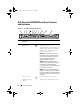
book.book Page 10 Monday, January 24, 2011 12:24 PM Dell PowerVault NX3500 Front-Panel Features and Indicators Figure 1-2. Front-Panel Features and Indicators 1 2 3 4 5 6 7 9 8 10 11 1 2 3 4 1 Item Indicator, Button, or Connector 1 Power-on indicator, power button Icon EST 2 3 Description The power-on indicator lights when the system power is on. The power button controls the DC power supply output to the system. When the system bezel is installed, the power button is not accessible.
book.book Page 11 Monday, January 24, 2011 12:24 PM Item Indicator, Button, or Connector 4 LCD panel Icon Description Provides system ID, status information, and system error messages. For more information on the LCD panel, see "LCD Panel Features" on page 12. NOTE: If the system is connected to AC power and an error has been detected, the LCD lights amber regardless of whether the system has been powered on. 5 system identification button Turns the system ID modes on and off.
book.book Page 12 Monday, January 24, 2011 12:24 PM LCD Panel Features The system's LCD panel provides system information and status and error messages to signify when the system is operating correctly or when the system needs attention. See "LCD Status Messages" on page 22 for information on specific status codes. The LCD backlight lights blue during normal operating conditions and lights amber to indicate an error condition.
book.book Page 13 Monday, January 24, 2011 12:24 PM Figure 1-3. LCD Panel Features 1 2 4 3 Item Buttons Description 1 Left Moves the cursor back in one-step increments. 2 Select Selects the menu item highlighted by the cursor. 3 Right Moves the cursor forward in one-step increments. During message scrolling: • Press once to increase scrolling speed. • Press again to stop. • Press again to return to default scrolling. • Press again to repeat the cycle.
book.book Page 14 Monday, January 24, 2011 12:24 PM Home Screen The Home screen displays user-configurable information about the system. This screen is displayed during normal system operation when there are no status messages or errors present. When the system is in standby mode, the LCD backlight turns off after five minutes of inactivity if there are no error messages. Press one of the three navigation buttons (Select, Left, or Right) to view the Home screen.
book.book Page 15 Monday, January 24, 2011 12:24 PM View Menu Option Description DRAC IP Displays the IPv4 or IPv6 addresses for the iDRAC6. Addresses include DNS (Primary and Secondary), Gateway, IP, and Subnet (IPv6 does not have Subnet). MAC Displays the MAC addresses for DRAC, iSCSIn, or NETn. NOTE: If the iDRAC6 Express card is not installed on the system, the MAC option displays the MAC addresses for BMC, iSCSIn, or NETn.
book.book Page 16 Monday, January 24, 2011 12:24 PM Hard-Drive Status Indicators Figure 1-4. Hard-Drive Indicators 2 1 1 drive-status indicator (green and amber) 2 drive-activity indicator (green) Drive-Status Indicator Pattern (RAID Only) Condition Blinks green two times per second Off Identify drive/preparing for removal Drive ready for insertion or removal NOTE: The drive status indicator remains off until all hard drives are initialized after system power is applied.
book.book Page 17 Monday, January 24, 2011 12:24 PM PowerVault NX3500 Back-Panel Features and Indicators Figure 1-5. Back-Panel Features and Indicators 1 2 3 4 5 Icon 6 7 10 8 9 11 Item Indicator, Button, or Connector Description 1 iDRAC6 Enterprise port Dedicated management port for the iDRAC6 Enterprise card. 2 Serial connector Connects a serial device to the system. 3 Video connector Connects a VGA display to the system. 4 USB connectors (2) Connect USB devices to the system.
book.book Page 18 Monday, January 24, 2011 12:24 PM Item Indicator, Button, or Connector 8 System status indicator Icon Description Lights blue during normal system operation. Both the systems management software and the identification buttons located on the front and back of the system can cause the indicator to flash blue to identify a particular system. Lights amber when the system needs attention due to a problem. 9 System identification button Turns the system ID modes on and off.
book.book Page 19 Monday, January 24, 2011 12:24 PM Indicator Indicator Code Link and activity indicators are off The NIC is not connected to the network. Link indicator is green The NIC is connected to a valid network link at 1000 Mbps. Link indicator is amber The NIC is connected to a valid network link at 10/100 Mbps. Activity indicator is green blinking Network data is being sent or received.
book.book Page 20 Monday, January 24, 2011 12:24 PM Figure 1-7. Power Supply Status Indicator 1 1 Power supply status LED Dell Backup Power Supply Front-Panel Features Figure 1-8.
book.book Page 21 Monday, January 24, 2011 12:24 PM Backup Power Supply Indicators Table 1-1 and Table 1-2 describes the possible visual and audible operating state indicators at start-up. Table 1-1.
book.book Page 22 Monday, January 24, 2011 12:24 PM Backup Power Supply Back-Panel Features Figure 1-9. Back-Panel Features 1 7 6 2 3 5 4 1 IEC 320 C-13 output receptacles (2) 2 fans (2) 3 interlock cover for C-14 input connectors (2) 4 grounding port 5 RS-232 ports (2) 6 USB ports (2) 7 LEDs (2) LCD Status Messages The system's control panel LCD provides status messages to signify when the system is operating correctly or when the system needs attention.
book.book Page 23 Monday, January 24, 2011 12:24 PM Table 1-3. LCD Status Messages Code Text Causes Corrective Actions E1000 Failsafe Check the system event voltage error. log for critical failure Contact events. support. Remove AC power to the system for 10 seconds and restart the system. If the problem persists, see "Getting Help" on page 113. E1114 Ambient Temp Ambient temperature has See "Troubleshooting exceeds reached a point outside of System Cooling allowed range. the allowed range.
book.book Page 24 Monday, January 24, 2011 12:24 PM Table 1-3. LCD Status Messages (continued) Code Text Causes E1229 CPU # VCORE Regulator failure. Reseat CPU. Specified processor Reseat the processor. See VCORE voltage regulator "Troubleshooting the has failed. Processor" on page 102. CPU # VTT Regulator failure. Reseat CPU. Specified processor VTT voltage regulator has failed. CPU Power Fault. Power cycle AC. A power fault was detected when powering up the processor.
book.book Page 25 Monday, January 24, 2011 12:24 PM Table 1-3. LCD Status Messages (continued) Code Text Causes Corrective Actions E1311 Fan module ## RPM exceeding range. Check fan. RPM of specified fan in specified module is outside of intended operating range. See "Troubleshooting System Cooling Problems" on page 96. E1313 Fan redundancy The system is no longer lost. Check fan redundant. Another fans. fan failure would put the system at risk of over-heating.
book.book Page 26 Monday, January 24, 2011 12:24 PM Table 1-3. LCD Status Messages (continued) Code Text Causes E141F CPU # protocol The system BIOS error. Power has reported a processor cycle AC. protocol error. Corrective Actions Remove AC power to the system for 10 seconds and restart the system. If the problem persists, see "Getting Help" on page 113. E1420 CPU Bus parity The system BIOS has error. Power reported a processor bus cycle AC. parity error.
book.book Page 27 Monday, January 24, 2011 12:24 PM Table 1-3. LCD Status Messages (continued) Code Text Causes Corrective Actions E161C Power Supply # (### W) lost AC power. Check PSU cables. Specified power supply is attached to the system, but it has lost its AC input. Check the AC power source for the specified power supply. If the problem persists, see "Troubleshooting Power Supply" on page 96. E1620 Power Supply # Specified power supply's (### W) AC AC input is outside of the power error.
book.book Page 28 Monday, January 24, 2011 12:24 PM Table 1-3. LCD Status Messages (continued) Code Text Causes E1710 I/O channel The system BIOS has check error. reported an I/O Review & clear channel check. SEL. Corrective Actions Check the SEL for more information and then clear the SEL. Remove AC power to the system for 10 seconds and restart the system. If the problem persists, see "Getting Help" on page 113.
book.book Page 29 Monday, January 24, 2011 12:24 PM Table 1-3. LCD Status Messages (continued) Code Text Causes Corrective Actions E1714 Unknown error. The system BIOS has Review & clear determined there has SEL. been an error in the system, but is unable to determine its origin. Check the SEL for more information and then clear the SEL. Remove AC power to the system for 10 seconds and restart the system. If the problem persists, see "Getting Help" on page 113.
book.book Page 30 Monday, January 24, 2011 12:24 PM Table 1-3. LCD Status Messages (continued) Code Text Causes E1A15 SAS cable B SAS cable B is missing failure. Check or bad. connection. Corrective Actions Reseat the cable. If the problem persists, replace cable. If the problem persists, see "Getting Help" on page 113. E1A1D Control panel USB cable not detected. Check cable. USB cable to the control panel is missing or bad. Reseat the cable. If the problem persists, replace cable.
book.book Page 31 Monday, January 24, 2011 12:24 PM Table 1-3. LCD Status Messages (continued) Code Text Causes Corrective Actions E2015 DMA Controller DMA controller failure. failure. Power cycle AC. Remove AC power to the system for 10 seconds and restart the system. If the problem persists, see "Getting Help" on page 113. E2016 E2017 Interrupt Interrupt controller Controller failure. failure. Power cycle AC. Remove AC power to the system for 10 seconds and restart the system.
book.book Page 32 Monday, January 24, 2011 12:24 PM Table 1-3. LCD Status Messages (continued) Code Text Causes E201A SuperIO SIO failure. failure. Power cycle AC. Corrective Actions Remove AC power to the system for 10 seconds and restart the system. If the problem persists, see "Getting Help" on page 113. Keyboard controller failure. Remove AC power to the system for 10 seconds and restart the system.If the problem persists, see "Getting Help" on page 113. E201B Keyboard Controller error.
book.book Page 33 Monday, January 24, 2011 12:24 PM Table 1-3. LCD Status Messages (continued) Code Text E2021 Incorrect Incorrect memory memory configuration. configuration. E2022 General failure during POST. Check screen message. E2110 Multibit Error The memory module in on DIMM ##. slot “##” has had a Reseat DIMM. multi-bit error (MBE). E2111 SBE log disabled on DIMM ##. Reseat DIMM.
book.book Page 34 Monday, January 24, 2011 12:24 PM Table 1-3. LCD Status Messages (continued) Code Text Causes Corrective Actions I1920 iDRAC6 Upgrade iDRAC6 has been Successful. upgraded successfully. W1228 RAID Controller battery capacity < 24hr. Warns predictively that the RAID battery has less than 24 hours of charge left. W1627 Power required > PSU wattage. Check PSU and config. The system configuration requires more power than what the power supply can provide.
book.book Page 35 Monday, January 24, 2011 12:24 PM Removing LCD Status Messages For faults associated with sensors, such as temperature, voltage, fans, and so on, the LCD message is automatically removed when that sensor returns to a normal state. For example, if temperature for a component goes out of range, the LCD displays the fault; when the temperature returns to the acceptable range, the message is removed from the LCD.
book.book Page 36 Monday, January 24, 2011 12:24 PM Table 1-4. System Messages Message Causes Corrective Actions Alert! iDRAC6 not The iDRAC6 is not Wait for the system to responding. responding to BIOS reboot. Rebooting. communication either because it is not functioning properly or has not completed initialization. The system will reboot. Alert! iDRAC6 not responding. Power required may exceed PSU wattage. The iDRAC6 has hung. Alert! Power required exceeds PSU wattage.
book.book Page 37 Monday, January 24, 2011 12:24 PM Table 1-4. System Messages (continued) Message Causes Alert! System fatal error during previous boot. An error caused the system to Check other system reboot. messages for additional information for possible causes. BIOS MANUFACTURING MODE detected. MANUFACTURING MODE will be cleared before the next boot. System reboot required for normal operation. System is in manufacturing mode. Reboot to take the system out of manufacturing mode.
book.book Page 38 Monday, January 24, 2011 12:24 PM Table 1-4. System Messages (continued) Message Causes Corrective Actions Current boot mode is set to UEFI. Please ensure compatible bootable media is available. Use the system setup program to change the boot mode as needed. The system failed to boot because UEFI boot mode is enabled in BIOS and the boot operating system is nonUEFI. Ensure that the boot mode is set correctly and that the proper bootable media is available.
book.book Page 39 Monday, January 24, 2011 12:24 PM Table 1-4. System Messages (continued) Message Causes Corrective Actions Local keyboard The USB ports are disabled may not work in the system BIOS. because all user accessible USB ports are disabled. If operating locally, power cycle the system and enter system setup program to change settings. Power down and restart the system from the power button, and then enter the System Setup program to enable the USB port(s). Manufacturing mode detected.
book.book Page 40 Monday, January 24, 2011 12:24 PM Table 1-4. System Messages (continued) Message Causes Corrective Actions Memory tests terminated by keystroke. POST memory test was terminated by pressing the spacebar. Information only. MEMTEST lane failure detected on x. Invalid memory configuration. Mismatched memory modules are installed. Ensure that the memory modules are installed in a valid configuration. See "General Memory Module Installation Guidelines" on page 67.
book.book Page 41 Monday, January 24, 2011 12:24 PM Table 1-4. System Messages (continued) Message Causes Corrective Actions Plug & Play Configuration Error. Error encountered in initializing PCIe device; faulty system board. Install the NVRAM_CLR jumper in the clear position (pins 1 and 3) and reboot the system. See Figure 5-1 for jumper location. If the problem persists, see "Troubleshooting an Expansion Card" on page 101. Quad rank DIMM Invalid memory detected after configuration.
book.book Page 42 Monday, January 24, 2011 12:24 PM Table 1-4. System Messages (continued) Message Causes Sector not found. Faulty hard drive. Seek error. Seek operation failed. Shutdown failure. General system error. The amount of Memory has been added or system memory has removed or a memory changed. module may be faulty. 42 About Your Solution Corrective Actions Replace the hard drive. Ensure that the SAS backplane cables are properly connected.
book.book Page 43 Monday, January 24, 2011 12:24 PM Table 1-4. System Messages (continued) Message Causes Corrective Actions The following DIMMs should match in Invalid memory configuration. The specified memory modules do not match in size, number of ranks, or number of data lanes. Ensure that the memory modules are installed in a valid configuration. See "General Memory Module Installation Guidelines" on page 67. geometry: x,x,... The following DIMMs should match in rank count: x,x,...
book.book Page 44 Monday, January 24, 2011 12:24 PM Table 1-4. System Messages (continued) Message Causes Corrective Actions TPM configuration operation honored. System will now reset. A TPM configuration Information only. command has been entered. The system will reboot and execute the command. TPM configuration operation is pending. Press (I) to Ignore OR (M) to Modify to allow this change and reset the system. This message displays during Enter I or M to proceed.
book.book Page 45 Monday, January 24, 2011 12:24 PM Table 1-4. System Messages (continued) Message Causes Corrective Actions Unexpected interrupt in protected mode. Improperly seated memory Reseat the memory modules. modules or faulty keyboard or See "Troubleshooting mouse controller chip. System Memory" on page 97. If the problem persists, see "Getting Help" on page 113. Unsupported CPU combination. Processor is not supported by Install a supported processor. the system. See "Processor" on page 73.
book.book Page 46 Monday, January 24, 2011 12:24 PM Table 1-4. System Messages (continued) Message Causes Warning: Control Panel is not installed. The control panel is not Install the control panel, or installed or has a faulty cable check the cable connections connection. between the display module, the control panel board, and the system board. See "Control Panel Assembly" on page 81. Warning! No micro Micro code update failed. code update loaded for processor n.
book.book Page 47 Monday, January 24, 2011 12:24 PM Table 1-4. System Messages (continued) Message Causes Corrective Actions Warning! Unsupported memory configuration detected. The memory configuration is not optimal. The recommended memory configuration is: . Invalid memory configuration. The system will run but with reduced functionality. Ensure that the memory modules are installed in a valid configuration. See "General Memory Module Installation Guidelines" on page 67.
book.book Page 48 Monday, January 24, 2011 12:24 PM Diagnostics Messages The system diagnostic utilities may issue messages if you run diagnostic tests on your system. See "Running the System Diagnostics" on page 105 for more information about system diagnostics. Alert Messages Systems management software generates alert messages for your system. Alert messages include information, status, warning, and failure messages for drive, temperature, fan, and power conditions.
book.book Page 49 Monday, January 24, 2011 12:24 PM Installing System Components 2 WARNING: While moving or transferring the system, it is recommended that you use the packaging material that shipped with the system and/or take care to avoid any damage due to shock or vibration. Recommended Tools • Key to the system keylock • #1 and #2 Phillips screwdrivers • Wrist grounding strap Inside the System CAUTION: Many repairs may only be done by a certified service technician.
book.book Page 50 Monday, January 24, 2011 12:24 PM Figure 2-1.
book.book Page 51 Monday, January 24, 2011 12:24 PM Front Bezel 1 Unlock the keylock at the left end of the bezel. 2 Lift up the release latch next to the key lock. 3 Rotate the left end of the bezel away from the front panel. 4 Unhook the right end of the bezel and pull the bezel away from the system. Figure 2-2.
book.book Page 52 Monday, January 24, 2011 12:24 PM Opening and Closing the System WARNING: Whenever you need to lift the system, get others to assist you. To avoid injury, do not attempt to lift the system by yourself. CAUTION: Many repairs may only be done by a certified service technician. You should only perform troubleshooting and simple repairs as authorized in your product documentation, or as directed by the online or telephone service and support team.
book.book Page 53 Monday, January 24, 2011 12:24 PM Figure 2-3. Opening and Closing the System 1 2 1 latch release lock 2 indent Closing the System 1 Place the cover onto the chassis and offset it slightly toward the back of the system, so that the two pins on the back edge of the cover fit over the corresponding slots on the back edge of the chassis. See Figure 2-3. 2 Slide the cover towards the front of the chassis till it snaps in position.
book.book Page 54 Monday, January 24, 2011 12:24 PM Optical Drive A slimline DVD+/-RW optical drive slides into the front panel and connects to the SATA controller on the system board. NOTE: DVD devices are data only. Removing an Optical Drive CAUTION: Many repairs may only be done by a certified service technician. You should only perform troubleshooting and simple repairs as authorized in your product documentation, or as directed by the online or telephone service and support team.
book.book Page 55 Monday, January 24, 2011 12:24 PM Figure 2-4.
book.book Page 56 Monday, January 24, 2011 12:24 PM Installing an Optical Drive CAUTION: Many repairs may only be done by a certified service technician. You should only perform troubleshooting and simple repairs as authorized in your product documentation, or as directed by the online or telephone service and support team. Damage due to servicing that is not authorized by Dell is not covered by your warranty. Read and follow the safety instructions that came with the product.
book.book Page 57 Monday, January 24, 2011 12:24 PM Hard Drives Your system supports two 3.5-inch SATA hard drives in 3.5-inch hot-swap hard-drive carriers. The hard drives are connected to a SAS backplane through hard-drive carriers and are hot-swappable. Removing a Hard-Drive Carrier CAUTION: Ensure that your operating system supports hot-swap drive installation. See the documentation supplied with the operating system. 1 If applicable, remove the front bezel. See "Front Bezel" on page 51.
book.book Page 58 Monday, January 24, 2011 12:24 PM Figure 2-5. Removing and Installing a Hard-Drive Carrier 1 3 2 1 release button 3 hard-drive carrier 2 hard-drive carrier handle Installing a Hard-Drive Carrier CAUTION: Many repairs may only be done by a certified service technician. You should only perform troubleshooting and simple repairs as authorized in your product documentation, or as directed by the online or telephone service and support team.
book.book Page 59 Monday, January 24, 2011 12:24 PM Removing a Hard Drive From a Hard-Drive Carrier CAUTION: Use only hard drives that have been tested and approved for use with the SAS/SATA backplane. CAUTION: When installing a hard drive, ensure that the adjacent drives are fully installed. Inserting a hard-drive carrier and attempting to lock its handle next to a partially installed carrier can damage the partially installed carrier's shield spring and make it unusable.
book.book Page 60 Monday, January 24, 2011 12:24 PM Installing a Hard Drive Into a Hard-Drive Carrier 1 Insert the hard drive into the hard-drive carrier with the connector end of the drive at the back. See Figure 2-6. 2 Align the screw holes on the hard drive with the back set of holes on the hard-drive carrier. When aligned correctly, the back of the hard drive will be flush with the back of the hard-drive carrier. 3 Attach the four screws to secure the hard drive to the hard-drive carrier.
book.book Page 61 Monday, January 24, 2011 12:24 PM Figure 2-7. Replacing an Expansion NIC Card 1 4 3 2 1 expansion-card latch 2 expansion NIC card 3 filler bracket 4 expansion-card riser 6 Unpack the new NIC card and prepare it for installation. For instructions, see the documentation accompanying the card. 7 Holding the expansion NIC card by its edges, position the card so that the card-edge connector aligns with the expansion-card connector on the expansion-card riser. See Figure 2-7.
book.book Page 62 Monday, January 24, 2011 12:24 PM 11 Close the system. See "Closing the System" on page 53. 12 Reconnect the system to its electrical outlet and turn the system on, including any attached peripherals. Cooling Shroud The system board shroud covers the processor, heat sink, and memory modules, and provides air flow to these components. Airflow is facilitated by the cooling fan modules, which are positioned directly beneath the cooling shroud.
book.book Page 63 Monday, January 24, 2011 12:24 PM Figure 2-8. Removing and Installing the Cooling Shroud 1 2 4 3 1 power distribution board shroud 2 system board shroud 3 tabs (2) 4 fan bay numbers Installing the Cooling Shroud CAUTION: Many repairs may only be done by a certified service technician. You should only perform troubleshooting and simple repairs as authorized in your product documentation, or as directed by the online or telephone service and support team.
book.book Page 64 Monday, January 24, 2011 12:24 PM Integrated Storage Controller Card Your system uses a dedicated expansion-card slot on the riser for an integrated SAS controller card that provides the integrated storage subsystem for your system’s internal hard drives. The controller uses SATA hard drives in RAID configurations. Removing the Integrated Storage Controller Card CAUTION: Many repairs may only be done by a certified service technician.
book.book Page 65 Monday, January 24, 2011 12:24 PM Figure 2-9.
book.book Page 66 Monday, January 24, 2011 12:24 PM Installing the Integrated Storage Controller Card CAUTION: Many repairs may only be done by a certified service technician. You should only perform troubleshooting and simple repairs as authorized in your product documentation, or as directed by the online or telephone service and support team. Damage due to servicing that is not authorized by Dell is not covered by your warranty. Read and follow the safety instructions that came with the product.
book.book Page 67 Monday, January 24, 2011 12:24 PM General Memory Module Installation Guidelines To ensure optimal performance of your system, observe the following general guidelines when configuring your system memory. NOTE: Memory configurations that fail to observe these guidelines can prevent your system from starting and producing any video output. • Except for memory channels that are unused, all populated memory channels must have identical configurations.
book.book Page 68 Monday, January 24, 2011 12:24 PM Figure 2-10. Replacing a Memory Module 1 2 3 1 memory module 3 alignment key 2 memory module socket ejectors (2) 6 Align the new memory module's edge connector with the alignment key of the memory module socket, and insert the memory module in the socket. NOTE: The memory module socket has an alignment key that allows you to install the memory module in the socket in only one way.
book.book Page 69 Monday, January 24, 2011 12:24 PM 11 Start up the system, press to enter the System Setup program, and check the System Memory setting on the main System Setup screen. The system should have already changed the value to reflect the newly installed memory. 12 If the value is incorrect, one or more of the memory modules may not be installed properly. Repeat step 2 through step 12 of this procedure, checking to ensure that the memory modules are firmly seated in their sockets.
book.book Page 70 Monday, January 24, 2011 12:24 PM 3 Remove the cooling shroud or power distribution board shroud as applicable. See "Cooling Shroud" on page 62. 4 Disconnect the fan’s power cable from the system board. See Figure 2-11. 5 Grasp the fan and slide it away from the fan assembly. See Figure 2-11. Figure 2-11.
book.book Page 71 Monday, January 24, 2011 12:24 PM Installing a Cooling Fan CAUTION: Many repairs may only be done by a certified service technician. You should only perform troubleshooting and simple repairs as authorized in your product documentation, or as directed by the online or telephone service and support team. Damage due to servicing that is not authorized by Dell is not covered by your warranty. Read and follow the safety instructions that came with the product.
book.book Page 72 Monday, January 24, 2011 12:24 PM 4 Remove the expansion NIC card from the expansion-card slot. See "Replacing an Expansion NIC Card" on page 60. 5 Pull back slightly on the two tabs at the front edge of the card and gently lift the front edge of the card off of the retention standoffs. As the card releases from the standoffs, the connector under the card disengages from the system board connector.
book.book Page 73 Monday, January 24, 2011 12:24 PM 9 If applicable, replace the expansion NIC card. See "Replacing an Expansion NIC Card" on page 60. 10 Close the system. See "Closing the System" on page 53. Reconnect the system to its electrical outlet and turn the system on, including any attached peripherals. Processor Removing a Processor CAUTION: Many repairs may only be done by a certified service technician.
book.book Page 74 Monday, January 24, 2011 12:24 PM CAUTION: The processor is held in its socket under strong pressure. Be aware that the release lever can spring up suddenly if not firmly grasped. 9 Position your thumb firmly over the processor socket-release lever and release the lever from the locked position. 10 Rotate the lever 90 degrees upward until the processor is released from the socket. See Figure 2-14. Figure 2-13.
book.book Page 75 Monday, January 24, 2011 12:24 PM Figure 2-14.
book.book Page 76 Monday, January 24, 2011 12:24 PM Installing a Processor CAUTION: Many repairs may only be done by a certified service technician. You should only perform troubleshooting and simple repairs as authorized in your product documentation, or as directed by the online or telephone service and support team. Damage due to servicing that is not authorized by Dell is not covered by your warranty. Read and follow the safety instructions that came with the product.
book.book Page 77 Monday, January 24, 2011 12:24 PM 11 Replace the cooling shroud. See "Installing the Cooling Shroud" on page 63. 12 Close the system. See "Closing the System" on page 53. 13 Reconnect the system to its electrical outlet and turn the system on, including any attached peripherals. 14 Press to enter the System Setup program, and check that the processor information matches the new system configuration. 15 Run the system diagnostics to verify that the new processor operates correctly.
book.book Page 78 Monday, January 24, 2011 12:24 PM 1 Disconnect the power cable from the power source. 2 Disconnect the power cable from the power supply and remove the Velcro straps that bundle and secure the system cables. NOTE: You may have to unlatch and lift the optional cable management arm if it interferes with power-supply removal. For information about the cable management arm, see the system’s rack documentation.
book.book Page 79 Monday, January 24, 2011 12:24 PM Installing a Power Supply 1 Verify that both power supplies are the same type and have the same maximum output power. NOTE: The maximum output power (shown in watts) is listed on the power supply label. 2 Slide the new power supply into the chassis until the power supply is fully seated and the release latch snaps into place. See Figure 2-15. NOTE: If you unlatched the cable management arm in step 2 of the previous procedure, relatch it.
book.book Page 80 Monday, January 24, 2011 12:24 PM Figure 2-16. Replacing the System Battery 1 3 2 1 positive side of battery connector 3 system battery 2 negative side of battery connector 3 Locate the battery socket. See Figure 5-1. CAUTION: To avoid damage to the battery connector, you must firmly support the connector while installing or removing a battery. 4 To remove the battery, push the metal tab away from the battery until the battery pops out. See Figure 2-16.
book.book Page 81 Monday, January 24, 2011 12:24 PM Control Panel Assembly NOTE: The LCD control panel assembly consists of two separate modules—the display module and the control panel circuit board. Use the following instructions to remove and install either module. Removing the Control Panel Board Assembly and the Control Panel Display Module CAUTION: Many repairs may only be done by a certified service technician.
book.book Page 82 Monday, January 24, 2011 12:24 PM Figure 2-17.
book.book Page 83 Monday, January 24, 2011 12:24 PM Installing the Control Panel Board Assembly and the Control Panel Display Module CAUTION: Many repairs may only be done by a certified service technician. You should only perform troubleshooting and simple repairs as authorized in your product documentation, or as directed by the online or telephone service and support team. Damage due to servicing that is not authorized by Dell is not covered by your warranty.
book.book Page 84 Monday, January 24, 2011 12:24 PM CAUTION: You must note the number of each hard drive and temporarily label them before removal so that you can replace them in the same locations. 3 Remove all hard drives. See "Removing a Hard-Drive Carrier" on page 57. 4 Disconnect the power cable from the SAS backplane. 5 Disconnect the SAS data cables from the backplane. See Figure 2-18. 6 Remove the optical drive cable, control panel cable, power cable, data cables, and USB cables.
book.book Page 85 Monday, January 24, 2011 12:24 PM Installing the SAS Backplane CAUTION: Many repairs may only be done by a certified service technician. You should only perform troubleshooting and simple repairs as authorized in your product documentation, or as directed by the online or telephone service and support team. Damage due to servicing that is not authorized by Dell is not covered by your warranty. Read and follow the safety instructions that came with the product.
book.book Page 86 Monday, January 24, 2011 12:24 PM Power Distribution Board The power distribution board is located in your system directly behind the power supply fan modules. This feature provides additional cooling to the power supplies through the power distribution shroud that routes airflow to the power supplies. See Figure 2-19. Removing the Power Distribution Board CAUTION: Many repairs may only be done by a certified service technician.
book.book Page 87 Monday, January 24, 2011 12:24 PM Figure 2-19.
book.book Page 88 Monday, January 24, 2011 12:24 PM Installing the Power Distribution Board CAUTION: Many repairs may only be done by a certified service technician. You should only perform troubleshooting and simple repairs as authorized in your product documentation, or as directed by the online or telephone service and support team. Damage due to servicing that is not authorized by Dell is not covered by your warranty. Read and follow the safety instructions that came with the product.
book.book Page 89 Monday, January 24, 2011 12:24 PM System Board Removing the System Board CAUTION: Many repairs may only be done by a certified service technician. You should only perform troubleshooting and simple repairs as authorized in your product documentation, or as directed by the online or telephone service and support team. Damage due to servicing that is not authorized by Dell is not covered by your warranty. Read and follow the safety instructions that came with the product.
book.book Page 90 Monday, January 24, 2011 12:24 PM 9 Remove all the memory modules. See "Replacing Memory Modules" on page 67. NOTE: To ensure proper reinstallation of memory modules, record the memory module socket locations. 10 Carefully route any loose cables away from the edges of the system board. 11 Remove the nine screws securing the system board to the chassis and then slide the system board assembly toward the front of the chassis.
book.book Page 91 Monday, January 24, 2011 12:24 PM Installing the System Board CAUTION: Many repairs may only be done by a certified service technician. You should only perform troubleshooting and simple repairs as authorized in your product documentation, or as directed by the online or telephone service and support team. Damage due to servicing that is not authorized by Dell is not covered by your warranty. Read and follow the safety instructions that came with the product.
book.book Page 92 Monday, January 24, 2011 12:24 PM 11 Replace the system battery. See "Replacing the System Battery" on page 79. 12 Reinstall the iDRAC6 Enterprise card. See "Replacing an Expansion NIC Card" on page 60. 13 Replace the cooling shroud. See "Installing the Cooling Shroud" on page 63. 14 Close the system. See "Closing the System" on page 53. 15 Reconnect the system to its electrical outlet and turn the system on, including any attached peripherals.
book.book Page 93 Monday, January 24, 2011 12:24 PM Troubleshooting Your System 3 Safety First—For You and Your System CAUTION: Many repairs may only be done by a certified service technician. You should only perform troubleshooting and simple repairs as authorized in your product documentation, or as directed by the online or telephone service and support team. Damage due to servicing that is not authorized by Dell is not covered by your warranty.
book.book Page 94 Monday, January 24, 2011 12:24 PM 3 Check the appropriate indicator on the NIC connector. See "NIC Indicator Codes" on page 18. • If the link indicator does not light, check all cable connections. • If the activity indicator does not light, the network driver files might be damaged or missing. Remove and reinstall the drivers if applicable. See the NIC's documentation. • Change the autonegotiation setting, if possible. • Use another connector on the switch or hub.
book.book Page 95 Monday, January 24, 2011 12:24 PM • Fans • Processor and heat sink • Memory modules • Hard-drive brackets • Cooling shroud 3 Ensure that all cables are properly connected. 4 Close the system. See "Closing the System" on page 53. 5 Reconnect the system to the electrical outlet and turn on the system. 6 Run the system board tests in the system diagnostics. See "Running the System Diagnostics" on page 105. If the tests fail, see "Getting Help" on page 113.
book.book Page 96 Monday, January 24, 2011 12:24 PM Troubleshooting Power Supply CAUTION: At least one power supply must be installed for the system to operate. Operating the system with only one power supply installed for extended periods of time can cause the system to overheat. 1 Reseat the power supply by removing and reinstalling it. See "Power Supplies" on page 77.
book.book Page 97 Monday, January 24, 2011 12:24 PM Troubleshooting a Fan CAUTION: Many repairs may only be done by a certified service technician. You should only perform troubleshooting and simple repairs as authorized in your product documentation, or as directed by the online or telephone service and support team. Damage due to servicing that is not authorized by Dell is not covered by your warranty.
book.book Page 98 Monday, January 24, 2011 12:24 PM 1 If the system is operational, run the appropriate online diagnostic test. See "Running the System Diagnostics" on page 105. If diagnostics indicates a fault, follow the corrective actions provided by the diagnostic program. 2 If the system is not operational, turn off the system and attached peripherals, and unplug the system from the power source. Wait at least 10 seconds and then reconnect the system to power.
book.book Page 99 Monday, January 24, 2011 12:24 PM 15 To troubleshoot an unspecified faulty memory module, replace the memory module in the first DIMM socket with a module of the same type and capacity. See "Replacing Memory Modules" on page 67. 16 Close the system. See "Closing the System" on page 53. 17 Reconnect the system to its electrical outlet, and turn on the system and attached peripherals.
book.book Page 100 Monday, January 24, 2011 12:24 PM Troubleshooting a Hard Drive CAUTION: Many repairs may only be done by a certified service technician. You should only perform troubleshooting and simple repairs as authorized in your product documentation, or as directed by the online or telephone service and support team. Damage due to servicing that is not authorized by Dell is not covered by your warranty.
book.book Page 101 Monday, January 24, 2011 12:24 PM Troubleshooting an Expansion Card CAUTION: Many repairs may only be done by a certified service technician. You should only perform troubleshooting and simple repairs as authorized in your product documentation, or as directed by the online or telephone service and support team. Damage due to servicing that is not authorized by Dell is not covered by your warranty.
book.book Page 102 Monday, January 24, 2011 12:24 PM Troubleshooting the Processor CAUTION: Many repairs may only be done by a certified service technician. You should only perform troubleshooting and simple repairs as authorized in your product documentation, or as directed by the online or telephone service and support team. Damage due to servicing that is not authorized by Dell is not covered by your warranty.
book.book Page 103 Monday, January 24, 2011 12:24 PM 3 Remove the following components from the system. See "Installing System Components" on page 49. • Hard drives • USB memory key • NIC hardware key • VFlash media • Expansion card and expansion-card riser • iDRAC6 Enterprise card • Power supply • Fans • Processor and heat sink • Memory modules • System Battery 4 Let the system dry thoroughly for at least 24 hours. 5 Reinstall the components you removed in step 3. 6 Close the system.
book.
book.book Page 105 Monday, January 24, 2011 12:24 PM Running the System Diagnostics 4 If you experience a problem with your system, run the diagnostics before calling for technical assistance. The purpose of the diagnostics is to test your system's hardware without requiring additional equipment or risking data loss. If you are unable to fix the problem yourself, service and support personnel can use diagnostics test results to help you solve the problem.
book.book Page 106 Monday, January 24, 2011 12:24 PM System Diagnostics Testing Options Click the testing option in the Main Menu window. Testing Option Function Express Test Performs a quick check of the system. This option runs device tests that do not require user interaction. Extended Test Performs a more thorough check of the system. This test can take an hour or longer. Custom Test Tests a particular device. Information Displays test results.
book.book Page 107 Monday, January 24, 2011 12:24 PM • Test Iterations—Selects the number of times the test is run. • Log Output File Pathname—Enables you to specify the diskette drive or USB memory key where the test log file is saved. You cannot save the file to a hard drive. Viewing Information and Results The following tabs in the Customize window provide information about the test and the test results: • Results — Displays the test that ran and the result.
book.
book.book Page 109 Monday, January 24, 2011 12:24 PM Jumpers and Connectors 5 This section provides specific information about the system jumpers. It also provides some basic information on jumpers and switches and describes the connectors on the system board. System Board Jumpers Figure 5-1 shows the location of the configuration jumpers on the system board. Table 5-1 lists the jumper settings. Table 5-1.
book.book Page 110 Monday, January 24, 2011 12:24 PM System Board Connectors Figure 5-1.
book.
book.book Page 112 Monday, January 24, 2011 12:24 PM Disabling a Forgotten Password The system's software security features include a system password and a setup password. The password jumper enables these password features or disables them and clears any password(s) currently in use. CAUTION: See “Protecting Against Electrostatic Discharge” in the safety instructions that came with the system. 1 Turn off the system, including any attached peripherals, and disconnect the system from the electrical outlet.
book.book Page 113 Monday, January 24, 2011 12:24 PM 6 Getting Help Contacting Dell For customers in the United States, call 800-WWW-DELL (800-999-3355). NOTE: If you do not have an active Internet connection, you can find contact information on your purchase invoice, packing slip, bill, or Dell product catalog. Dell provides several online and telephone-based support and service options. Availability varies by country and product, and some services may not be available in your area.
book.
book.book Page 115 Monday, January 24, 2011 12:24 PM Index B back-panel features and indicators, 17 backup power supply, 20 battery (system) replacing, 79 bezel, 51 C cabling optical drive, 54 CD drive troubleshooting, 99 CD/DVD drive See optical drive. removing, 62 cover closing, 53 opening, 52 D damaged systems troubleshooting, 94 Dell contacting, 113 diagnostics advanced testing options, 106 when to use, 105 DIMMs See memory modules (DIMMs).
book.
book.book Page 117 Monday, January 24, 2011 12:24 PM power supplies indicators, 19 replacing, 79 SAS backplane board installing, 85 removing, 83 power supply troubleshooting, 96 SAS controller card installing, 66 removing, 64 processor removing, 73, 76 See processor.
book.