
Deployment Guide


For more information, see Running PowerVault NAS IDU.
9. Set up your MD storage array using the MDSM.
For more information, see Setting Up Your MD Storage Solution.
10. Run the NAS Manager Configuration Wizard.
For more information, see NAS Manager Configuring Wizard.
Topics:
• Choosing The Switch Topology
• Cabling Overview
• Dedicated SAN High-Availability (Recommended)
• Dedicated SAN Solution In The Non-Redundant Option
• All-In-One High-Availability Option
• All-In-One Non-Redundant Option
• Preparing Your Management Station
Choosing The Switch Topology
The PowerVault NX3600/NX3610 supports multiple switch topologies. Choose the ideal topology for your environment and cable the
solution accordingly. For more information on the cabling requirements for each of the topologies, see Cabling Overview.
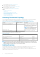
Table 2. Switch Topologies for PowerVault NX3600/NX3610 in the Non-Redundant and High Availability Options
Topology Number of Switches Description
Dedicated SAN — High Availability (HA) 4 This topology leverages the best practices of the
industry relating to iSCSI and separates the SAN
and LAN/Client traffic. The client cables are
connected to a client switch and the SAN cables
are connected to a SAN switch.
NOTE: Dedicated SAN-High Availability
(HA) is the recommended topology.
Dedicated SAN — Non-Redundant 2
All-in-one solution — HA 2 A basic topology where the SAN and the client
cables are connected to the same switch.
All-in-one solution — Non-Redundant 1
Ensure the following settings are enabled in the SAN and client switches:
Table 3. Switch Settings
Client/Primary Network SAN Network
Jumbo Frames Enabled (9216 MTU) Recommended Required
Portfast Enabled Required Required
Flow Control Enabled Recommended Required
IPv6 Required (during initial deployment) Required
NOTE: Dell PowerConnect switches must be configured with an MTU size of 9216 or greater to accept frames of size
9000 MTU. Non-Dell switches may require a different MTU configuration for similar frame sizes. For more information
on MTU configuration for non-Dell switches, see the switch-specific manual.
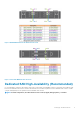
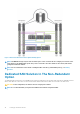
Cabling Overview
The following figures give an overview of the cabling for the Dedicated SAN – High Availability (HA) solution. If one of the non-HA
topologies is chosen, instead of splitting the cables between switches A and B, the cables will go to the single switch A.
For example, if you do not use two client switches, all client connection cables will go to client switch A. Cabling illustrations for other
available topologies are detailed further down in the document.
8
Setting Up The Environment