Dell FluidFS NAS Solutions NX3600/NX3610 Deployment Guide
Notes, Cautions, and Warnings NOTE: A NOTE indicates important information that helps you make better use of your computer. CAUTION: A CAUTION indicates either potential damage to hardware or loss of data and tells you how to avoid the problem. NOTE: A WARNING indicates a potential for property damage, personal injury, or death. © 2013 Dell Inc.
Contents 1 PowerVault NX3600/NX3610 NAS Appliance Overview.................................................................... 5 Supported Hardware.............................................................................................................................................................5 Supported Software..............................................................................................................................................................
Mapping Users Automatically.............................................................................................................................................27 Creating NAS Volumes....................................................................................................................................................... 28 Creating CIFS Shares..................................................................................................................................................
1 PowerVault NX3600/NX3610 NAS Appliance Overview The Dell PowerVault NX3600 and NX3610 NAS appliances that work with PowerVault MD32x0i and MD36x0i iSCSI deployments help provide unified storage solutions with access to block and file data. The PowerVault NX3600 series uses the Dell Fluid File System (FluidFS) to enable both performance and capacity to scale without SAN or application downtime.
Administrator’s Guide Provides information about configuring and managing the system. CLI Reference Guide Provides information about set of commands to view, edit, add, delete, enable, disable, and set NAS cluster solution entities, such as exports, shares, volumes, and accounts. System Placemat Provides information on how to set up the hardware and install the software on your Dell FluidFS NAS solution.
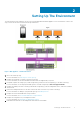
2 Setting Up The Environment The following are the steps required to set up your PowerVault NX3600/NX3610 NAS Appliance. For more information on each of the steps, see the relevant sections mentioned in the procedure below. Figure 1. NAS Appliance – Hardware Overview 1. Choose the switch topology. For more information see, Choosing The Switch Topology. 2. Complete the setting up of your NAS controller(s) in the rack.
For more information, see Running PowerVault NAS IDU. 9. Set up your MD storage array using the MDSM. For more information, see Setting Up Your MD Storage Solution. 10. Run the NAS Manager Configuration Wizard. For more information, see NAS Manager Configuring Wizard.
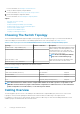
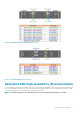
Figure 2. NX3600/NX3610 Controller Network Connections Figure 3. PowerVault MD Network Connections Dedicated SAN High-Availability (Recommended) It is recommended to isolate the SAN traffic from the LAN or client traffic with redundant switches for HA. All the client cables are split between the redundant client switches, and the SAN/Internal network cables are split between the redundant SAN switches. The MD controller management ports are split between the redundant client switches.
Figure 4. Dedicated SAN Solution in the High Availability Option NOTE: The MD32x0i storage array has four iSCSI data ports on each controller. Do not configure ports 2 and 3 on the same subnets as the FluidFS NAS system. They can be connected to the same switch for other clients, but must be configured on different subnets. NOTE: For more information on the details of cabling the NAS controller(s) and the MD system(s), see Cabling Overview.
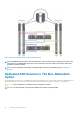
Figure 5. Dedicated SAN Solution in the Non-Redundant Option NOTE: For more information on the details of cabling the NAS controller(s) and the MD system(s), see Cabling Overview. All-In-One High-Availability Option In the all-in-one high-availability option, the redundant switches are stacked and host both SAN/Internal and client network traffic. The SAN/Internal and client cables are split between the redundant switches.
Figure 6. All-in-One High-Availability Option NOTE: For more information on the details of cabling the NAS controller(s) and the MD system(s), see Cabling Overview. All-In-One Non-Redundant Option In the all-in-one non-redundant option, both the SAN/Internal and client cables are connected to the same switch. CAUTION: In this configuration, the switch is a single point of failure. NOTE: It is recommended that you separate the SAN and client subnets using virtual LANs.
Figure 7. All-in-One Non-Redundant Option NOTE: For more information on the details of cabling the NAS controller(s) and the MD system(s), see Cabling Overview. Preparing Your Management Station A management station is required to manage and configure the NAS cluster solution. The NAS cluster solution can be accessed using either the CLI or the Dell PowerVault NAS Manager. NOTE: You can either log on to the CLI or the NAS Manager.
3 Running NAS IDU The Dell NAS Initial Deployment Utility (IDU) guides you through the steps necessary to set up the network configuration and pair the controllers together. It also starts the process of pairing the system to the PowerVault MD32x0i/MD36x0i storage appliances. Before running the NAS IDU, ensure that: • • You complete the PowerVault FluidFS NAS Setup worksheet to determine your network configuration and IP address allocation for your controllers before executing this utility.
• If un-configured NAS controllers are not discovered automatically, go to step 3. 3. On the NAS Discovery screen, click Next. The MAC Controller Discovery screen is displayed. 4. Connect a monitor and keyboard to an un-configured controller. The Controller MAC Address is displayed on the monitor. 5. On the MAC Controller Discovery screen, in MAC Address, enter the MAC address that is displayed on the monitor connected to the un-configured NAS controller. 6.
21. Click Next. The iSCSI Target Discovery screen is displayed. 22. In iSCSI Discovery Address for MD Array, enter one of the iSCSI port IP addresses of the PowerVault MD array for the iSCSI target. NOTE: The NX3610 supports two MD storage arrays. In version 01.01.02.016 of the NAS IDU, if a second array is not attached to the NX3610 cluster, enter the IP address of the single storage array twice. 23. Click Next.
4 Setting Up Your MD Storage Solution Before following the instructions in this section, ensure that you have discovered and completed the initial configuration (naming, assigning iSCSI, and management port IPs) of your PowerVault MD32x0i/MD36x0i storage arrays in accordance with the topology you plan to use. This section provides the steps necessary to configure the host group and virtual disks that are required for the NAS cluster solution.
• • All four iSCSI host ports must be configured to use different individual subnets. Two of the four iSCSI host ports can be used for additional block level iSCSI access by other hosts. NOTE: The NX3600 connects to two of the four ports configured. Enabling Jumbo Frames On The MD Storage Array To enable jumbo frames on all the iSCSI ports on the MD storage array: 1. In the PowerVault MDSM, select the Hardware tab. 2. Right-click the relevant controller. 3. Select Configure > iSCSI Ports.
One Disk Group (RAID 1/10), One Hot Spare Space This option consists of one RAID 1/10 disk group with two virtual disks and a single hot spare. The single RAID 1/10 disk group is made up of eleven, 2 TB hard drives. In RAID 1/10, the total space available for virtual disks is 10 TB as the usable capacity is half of the physical disks in the disk group. The NAS cluster requires pairs of equal sized virtual disks.
two hard disks are allocated for parity. The NAS cluster requires pairs of equal sized virtual disks. Therefore, each disk group is divided into a single 8 TB virtual disk utilizing all available space in its disk group. You have 16 TB space to be allocated for the NAS cluster. High Availability A RAID 6 disk group can continue to execute read and write requests to all of its virtual disks after any two concurrent disk failures.
Creating Disk Groups Automatically NOTE: The following steps apply to PowerVault MDSM versions 10.84.x6.25 and later. To create disk groups automatically: 1. Launch the PowerVault MDSM software on the management station. 2. Select the MD storage array you plan to use for your NAS storage. 3. Start the Create Disk Group Wizard using one of the following methods: • • On the Storage & Copy Services tab, select Unconfigured Capacity and then select Create Disk Group from the pop-up menu. In version 10.80.x6.
NOTE: The disk group name must not exceed 30 characters. 6. In Physical Disk selection choices select Manual and click Next. The RAID Level and Capacity screen is displayed. 7. In the RAID Level and Capacity window, select the appropriate RAID level from the RAID level list. You can select RAID levels 1/10, 5, or 6. Depending on the RAID level chosen, the physical disks available for the selected RAID level are displayed in Unselected Physical Disks table. 8.
NOTE: The size of the virtual disk must be equal to or less than the free capacity. 4. In the Virtual Disk name field, enter a relevant name for the virtual disk. 5. Click Next. The Specify Capacity/Name screen is displayed. 6. In the Map to host field, select Map Later. 7. In the Virtual Disk I/O characteristics type field, select File system (typical). 8. Click Finish. The Create Virtual Disk – Completed screen is displayed. 9. Click Yes to create a new virtual disk.
11. Click Finish. The Creation Successful (Define Host) screen is displayed. 12. Click Yes to define another host. Repeat step 2 to step 10 to create another host. A host must be created for each NAS controller that is a member of the cluster. Adding Virtual Disks To A Host Group To add virtual disks to a host group: 1. In the PowerVault MDSM, right-click the host group you created. 2. Select Add LUN Mapping. In version 10.80.x6.47 of the PowerVault MDSM, select Define > Additional Mapping. 3.
5 Running The NAS Manager Configuration Wizard The NAS Manager Configuration Wizard is the final step in completing the PowerVault NAS cluster solution configuration and integrating the solution into the environment. In addition to formatting and starting the file system, you can set up the DNS, time management, user identification, authentication parameters, and monitoring options. You can leave the wizard at any time by selecting another page from the navigation pane.
NOTE: You must use an NTP server. If the clients and the NAS cluster get out of sync for more than five minutes, the clients cannot connect to the cluster. 3. Click Next. The Configuration Wizard (E-mail Configuration) step 3 of 14 screen is displayed. Configuring SMTP NOTE: It is highly recommended that you configure an SMTP server for e-mail alerts in case of issues with the cluster solution. To configure SMTP: 1.
Creating and Changing Admin Passwords By default, the Local CIFS Administrator password is randomized and needs to be set before CIFS shares can be managed. It is highly recommended that you change the local admin password. NOTE: To change the admin password or the CIFS Administrator password, you must enter the default admin password. The default admin password is Stor@ge!. In the Configuration Wizard (Change Passwords) step 7 of 14, click Next.
1. In the Configuration Wizard (Cross-protocol User Mapping) step 11 of 14 screen, select Map users in Active Directory to users in the UNIX repository automatically. NOTE: By default, Map unmapped users to the guest account is selected. 2. Click Next. The Configuration Wizard (NAS Volumes Configuration) step 12 of 14 screen is displayed. Creating NAS Volumes NAS volumes can be created with file access security styles of NTFS, UNIX, or mixed.
5. Define the client machines that are allowed access to the NFS export by selecting one of the following: • • • • All Client Machines A single Client Machine All Client Machines in a specific network All Client Machines in a specific netgroup 6. Click Save Changes. The Configuration Wizard (NFS export) step 14 of 14 screen with the existing NFS exports is displayed. 7. To add additional NFS exports, click Add and repeat this procedure. 8. Click Next. The system Configuration Wizard is complete.
6 PowerVault FluidFS NAS Setup Worksheet Complete the worksheet to record the layout of your PowerVault FluidFS NAS. Use this worksheet while performing the network configuration steps in the NAS IDU.
NAS iSCSI Network Network MTU ○ 9000 (Jumbo Frames) Subnet Mask: SAN Network A NAS Appliance 0, Controller 0 IP: NAS Appliance 1, Controller 2 IP: NAS Appliance 0, Controller 1 IP: NAS Appliance 1, Controller 3 IP: SAN Network B NAS Appliance 0, Controller 0 IP: NAS Appliance 1, Controller 2 IP: NAS Appliance 0, Controller 1 IP: NAS Appliance 1, Controller 3 IP: MD-Series iSCSI Network (iSCSI Target Discovery Address) Network MTU ○ 9000 (Jumbo Frames) Subnet Mask: SAN Network A MD Array 0 MD Ar
7 Getting Help Topics: • • Contacting Dell Documentation Feedback Contacting Dell NOTE: Dell provides several online and telephone-based support and service options. If you do not have an active Internet connection, you can find contact information on your purchase invoice, packing slip, bill, or Dell product catalog. Availability varies by country and product, and some services may not be available in your area. To contact Dell for sales, technical support, or customer-service issues: 1. Go to dell.