Dell FluidFS NAS Solutions NX3600/NX3610 Deployment Guide
Notes, Cautions, and Warnings NOTE: A NOTE indicates important information that helps you make better use of your computer. CAUTION: A CAUTION indicates either potential damage to hardware or loss of data and tells you how to avoid the problem. WARNING: A WARNING indicates a potential for property damage, personal injury, or death. © 2013 Dell Inc.
Contents Notes, Cautions, and Warnings...................................................................................................2 1 PowerVault NX3600/NX3610 NAS Appliance Overview.......................................................5 Supported Hardware................................................................................................................................................5 Supported Software.....................................................................................
Creating A Host.......................................................................................................................................................26 Adding Virtual Disks To A Host Group....................................................................................................................27 Accessing The NAS Manager Web Interface........................................................................................................
PowerVault NX3600/NX3610 NAS Appliance Overview 1 The Dell PowerVault NX3600 and NX3610 NAS appliances that work with PowerVault MD32x0i and MD36x0i iSCSI deployments help provide unified storage solutions with access to block and file data. The PowerVault NX3600 series uses the Dell Fluid File System (FluidFS) to enable both performance and capacity to scale without SAN or application downtime.
Owner’s Manual Provides information about system features and describes how to troubleshoot the system and install or replace system components. Administrator’s Guide Provides information about configuring and managing the system. CLI Reference Guide Provides information about set of commands to view, edit, add, delete, enable, disable, and set NAS cluster solution entities, such as exports, shares, volumes, and accounts.
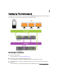
Setting Up The Environment 2 The following are the steps required to set up your PowerVault NX3600/NX3610 NAS Appliance. For more information on each of the steps, see the relevant sections mentioned in the procedure below. Figure 1. NAS Appliance – Hardware Overview 1. Choose the switch topology. For more information see, Choosing The Switch Topology. 2. Complete the setting up of your NAS controller(s) in the rack.
4. Complete the cabling of the NAS controller(s) and the MD storage array(s) with the management station, SAN network, and the client network. 5. Connect the management station to the same switch as the client connections on your NAS controller(s). For more information on cabling for your particular topology, see Cabling Overview. 6. Complete the PowerVault FluidFS NAS Setup worksheet. For more information, see PowerVault FluidFS NAS Setup Worksheet. 7.
NOTE: Dell PowerConnect switches must be configured with an MTU size of 9216 or greater to accept frames of size 9000 MTU. Non-Dell switches may require a different MTU configuration for similar frame sizes. For more information on MTU configuration for non-Dell switches, see the switch-specific manual. Cabling Overview The following figures give an overview of the cabling for the Dedicated SAN – High Availability (HA) solution.
Figure 3. PowerVault MD Network Connections Dedicated SAN High-Availability (Recommended) It is recommended to isolate the SAN traffic from the LAN or client traffic with redundant switches for HA. All the client cables are split between the redundant client switches, and the SAN/Internal network cables are split between the redundant SAN switches. The MD controller management ports are split between the redundant client switches.
Figure 4. Dedicated SAN Solution in the High Availability Option NOTE: The MD32x0i storage array has four iSCSI data ports on each controller. Do not configure ports 2 and 3 on the same subnets as the FluidFS NAS system. They can be connected to the same switch for other clients, but must be configured on different subnets. NOTE: For more information on the details of cabling the NAS controller(s) and the MD system(s), see Cabling Overview.
Figure 5. Dedicated SAN Solution in the Non-Redundant Option NOTE: For more information on the details of cabling the NAS controller(s) and the MD system(s), see Cabling Overview. All-In-One High-Availability Option In the all-in-one high-availability option, the redundant switches are stacked and host both SAN/Internal and client network traffic. The SAN/Internal and client cables are split between the redundant switches.
Figure 6. All-in-One High-Availability Option NOTE: For more information on the details of cabling the NAS controller(s) and the MD system(s), see Cabling Overview. All-In-One Non-Redundant Option In the all-in-one non-redundant option, both the SAN/Internal and client cables are connected to the same switch. CAUTION: In this configuration, the switch is a single point of failure. NOTE: It is recommended that you separate the SAN and client subnets using virtual LANs.
Figure 7. All-in-One Non-Redundant Option NOTE: For more information on the details of cabling the NAS controller(s) and the MD system(s), see Cabling Overview. Preparing Your Management Station A management station is required to manage and configure the NAS cluster solution. The NAS cluster solution can be accessed using either the CLI or the Dell PowerVault NAS Manager. NOTE: You can either log on to the CLI or the NAS Manager.
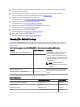
Running NAS IDU 3 The Dell NAS Initial Deployment Utility (IDU) guides you through the steps necessary to set up the network configuration and pair the controllers together. It also starts the process of pairing the system to the PowerVault MD32x0i/MD36x0i storage appliances. Before running the NAS IDU, ensure that: • You complete the PowerVault FluidFS NAS Setup worksheet to determine your network configuration and IP address allocation for your controllers before executing this utility.
The NAS Initial Deployment Utility screen is displayed. 2. Click Next. The NAS Discovery screen is displayed. – 3. All un-configured NAS appliances are displayed in the NAS Discovery screen. Select the appropriate NAS appliance model and go to step 8. – If un-configured NAS controllers are not discovered automatically, go to step 3. On the NAS Discovery screen, click Next. The MAC Controller Discovery screen is displayed. 4. Connect a monitor and keyboard to an un-configured controller.
16. Click Next. The Internal interconnect network screen is displayed. 17. If blank, enter the IP addresses for the Controllers, Winbind, and Subnet Mask. The NAS iSCSI network screen is displayed. 18. Enter the IP addresses for the following: – SAN Network A – SAN Network B – Subnet mask For SAN Networks A and B, enter the first IP address and as you enter the SAN network IP addresses the IP Range for Controllers get updated. 19.
Setting Up Your MD Storage Solution 4 Before following the instructions in this section, ensure that you have discovered and completed the initial configuration (naming, assigning iSCSI, and management port IPs) of your PowerVault MD32x0i/MD36x0i storage arrays in accordance with the topology you plan to use. This section provides the steps necessary to configure the host group and virtual disks that are required for the NAS cluster solution.
• Two of the four iSCSI host ports can be used for additional block level iSCSI access by other hosts. NOTE: The NX3600 connects to two of the four ports configured. Enabling Jumbo Frames On The MD Storage Array To enable jumbo frames on all the iSCSI ports on the MD storage array: 1. In the PowerVault MDSM, select the Hardware tab. 2. Right-click the relevant controller. 3. Select Configure → iSCSI Ports. The Configure iSCSI Ports screen is displayed. 4. Click Advanced Port Settings. 5.
failures, with the hot spare, there can be three concurrent disk drive failures before read and write requests cannot be executed. One Disk Group (RAID 1/10), One Hot Spare Space This option consists of one RAID 1/10 disk group with two virtual disks and a single hot spare. The single RAID 1/10 disk group is made up of eleven, 2 TB hard drives. In RAID 1/10, the total space available for virtual disks is 10 TB as the usable capacity is half of the physical disks in the disk group.
High Availability A RAID 5 disk group can continue to execute read and write requests to all its virtual disks after a single disk failure. As long as there is enough time to rebuild between failures, with hot spares, there can be three disk drive failures before read and write requests cannot be executed. Two Disk Groups (RAID 6), Zero Hot Spares Space This option consists of two RAID 6 disk groups with a single virtual disk in each group and no hot spares.
One Disk Group (RAID 5), One Hot Spare CAUTION: Due to the large capacity and number of physical disks, the limitation to this option is the rebuild time. If two disks fail simultaneously, data loss may occur. Space This option consists of one RAID 5 disk group with two virtual disks and a single hot spare. The disk group is made up of eleven, 2 TB physical disks with a total size of 20 TB. The NAS cluster requires pairs of equal sized virtual disks.
The Introduction (Create Disk Group) window is displayed. 4. In the Introduction (Create Disk Group) window, click Next. The Disk Group Name & Physical Disk Selection window is displayed. 5. Type a name for the disk group in Disk Group Name. It is recommended that you use the name of the NAS cluster appended by disk group and number for the disk group name. For example, NX3600-Disk-Group-0. NOTE: The disk group name must not exceed 30 characters. 6.
8. In the Unselected Physical Disks table, select the relevant disk group capacity, and click Add. NOTE: You can select multiple physical disks at the same time by holding Ctrl or Shift and selecting additional physical disks. To view the capacity of the new disk group, click Calculate Capacity. 9. Click Finish. The Disk Group Created screen is displayed. If you are going to use two disk groups, repeat step 3 to step 9 and then proceed to Creating Virtual Disks.
Introduction (Create Virtual Disk) screen is displayed. NOTE: The size of the virtual disk must be equal to or less than the free capacity. 4. In the Virtual Disk name field, enter a relevant name for the virtual disk. 5. Click Next. The Specify Capacity/Name screen is displayed. 6. In the Map to host field, select Map Later. 7. In the Virtual Disk I/O characteristics type field, select File system (typical). 8. Click Finish. The Create Virtual Disk – Completed screen is displayed. 9.
The Specify Host Port Identifiers (Define Host) screen is displayed. 5. Select the host port identifier from the Add by selecting a known unassociated host port identifier list. 6. Type the host name in User label and suffix the host name with IQN. 7. Click Add. 8. Click Next. The Specify Host Type (Define Host) screen is displayed. 9. Select Linux from the Host type (operating system) list. 10. Click Next. The Preview (Define Host) screen is displayed. 11. Click Finish.
3. Click Install Certificate. The Certificate Import Wizard is displayed. 4. Click Next. The Certificate Store screen is displayed. 5. Verify that Automatically select the certificate store based on the type of certificate is selected and click Next. The Completing the Certificate Import Wizard screen is displayed. 6. Click Finish. A message prompts you that the certificate is imported successfully. 7. Click OK. The certificate window is displayed. 8. In the Certificate window, click OK. 9.
5 Running The NAS Manager Configuration Wizard The NAS Manager Configuration Wizard is the final step in completing the PowerVault NAS cluster solution configuration and integrating the solution into the environment. In addition to formatting and starting the file system, you can set up the DNS, time management, user identification, authentication parameters, and monitoring options. You can leave the wizard at any time by selecting another page from the navigation pane.
Configuring SMTP NOTE: It is highly recommended that you configure an SMTP server for e-mail alerts in case of issues with the cluster solution. To configure SMTP: 1. In the Configuration Wizard (E-mail Configuration) step 3 of 14 screen, click Add SMTP server. The Configuration Wizard (Add SMTP server) step 3 of 14 is displayed. 2. In Mail server or relay , add the SMTP server address. 3. In Description, enter the description for the SMTP server and click Save Changes.
3. Click Next. The Configuration Wizard (System Stop/Start) step 6 of 14 screen is displayed. You can choose to start the file system at this time or start it later by skipping this step. The file system must be started in order to serve up files and shares. 4. To start the file system, click Next. The Configuration Wizard (Change Passwords) step 7 of 14 screen is displayed.
3. Click Next. The Configuration Wizard (Identity Management Database) step 10 of 14 screen is displayed. Providing UNIX Identity Database Values The NAS solution supports NIS and LDAP for UNIX user identity management. To provide UNIX identity database values: 1. In the Configuration Wizard (Identity Management Database) step 10 of 14 screen, select the appropriate UNIX identity database. If NIS and LDAP are not used in the environment, select Users are not defined in an external user database. 2.
Creating CIFS Shares To create CIFS shares: 1. In the Configuration Wizard (Add CIFS Shares) step 13 of 14 screen, select the volume from the NAS Volume list to add CIFS Share. 2. Select either General-access share or CIFS share, containing a user-based directory tree and enter the appropriate information. NOTE: You cannot add a CIFS share if a shared folder is not created. 3. Click Save Changes. A CIFS share is created and the Configuration Wizard (CIFS Shares) step 13 of 14 screen is displayed.
1. Select Cluster Management → Network → Subnets. The Subnets screen displays all the available subnets. 2. Click the Primary subnet. The Add/Edit Subnet screen is displayed. 3. In VIP address, add additional client VIP addresses, as required. NOTE: If you need more than four VIPs, click Add VIP. 4. Click Save Changes. Troubleshooting LUNs To ensure that the LUNs are available to all controllers: 1. Verify if the correct NAS controller IQN is entered in the PowerVault MD Storage Manager (MDSM).
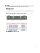
PowerVault FluidFS NAS Setup Worksheet 6 Complete the worksheet to record the layout of your PowerVault FluidFS NAS. Use this worksheet while performing the network configuration steps in the NAS IDU.
Primary Client Network MD Array 1 Controller 0, Management IP: Controller1, Management IP: Interconnect (Private) Network Select a private Class C subnet ○ 10.255.254.x ○ 172.31.254.x ○ 192.168.254.x ○___.___.___.
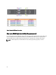
Getting Help 7 Contacting Dell NOTE: Dell provides several online and telephone-based support and service options. If you do not have an active Internet connection, you can find contact information on your purchase invoice, packing slip, bill, or Dell product catalog. Availability varies by country and product, and some services may not be available in your area. To contact Dell for sales, technical support, or customer-service issues: 1. Go to dell.com/contactdell. 2.