Dell Precision 3431 Small Form Factor Service-Handbuch Vorschriftenmodell: D11S Vorschriftentyp: D11S004
Anmerkungen, Vorsichtshinweise und Warnungen ANMERKUNG: Eine ANMERKUNG macht auf wichtige Informationen aufmerksam, mit denen Sie Ihr Produkt besser einsetzen können. VORSICHT: Ein VORSICHTSHINWEIS warnt vor möglichen Beschädigungen der Hardware oder vor Datenverlust und zeigt, wie diese vermieden werden können. WARNUNG: Mit WARNUNG wird auf eine potenziell gefährliche Situation hingewiesen, die zu Sachschäden, Verletzungen oder zum Tod führen kann. © 2019 Dell Inc. oder ihre Tochtergesellschaften.
Inhaltsverzeichnis 1 Arbeiten am Computer.................................................................................................................. 6 Sicherheitshinweise............................................................................................................................................................... 6 Ausschalten des Computers — Windows 10.....................................................................................................................
Kühlkörper und Lüfter......................................................................................................................................................... 43 Entfernen des Kühlkörpers und des Kühlkörperlüfters............................................................................................. 43 Installieren des Kühlkörpers und des Kühlkörperlüfters............................................................................................ 44 Eingriffschalter....................
6 Wie Sie Hilfe bekommen............................................................................................................. 98 Kontaktaufnahme mit Dell.................................................................................................................................................. 98 Anhang A: Staubfilter für Dell Precision 3431 Small Form Factor....................................................... 99 Anhang B: Einbauen der USB-Type-C-Karte........................................
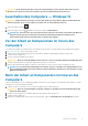
1 Arbeiten am Computer Themen: • • • • Sicherheitshinweise Ausschalten des Computers — Windows 10 Vor der Arbeit an Komponenten im Innern des Computers Nach der Arbeit an Komponenten im Inneren des Computers Sicherheitshinweise Beachten Sie folgende Sicherheitsrichtlinien, damit Ihr Computer vor möglichen Schäden geschützt und Ihre eigene Sicherheit sichergestellt ist.
VORSICHT: System wird heruntergefahren, wenn die Seitenabdeckungen entfernt werden, während das System in Betrieb ist. Das System lässt sich nicht einschalten, wenn die Seitenabdeckung nicht angebracht ist. Ausschalten des Computers — Windows 10 VORSICHT: Um Datenverlust zu vermeiden, speichern und schließen Sie alle geöffneten Dateien und beenden Sie alle aktiven Programme, bevor Sie den Computer ausschalten oder die Seitenabdeckung entfernen. 1. Klicken oder tippen Sie auf das 2.
2 Technologie und Komponenten Dieses Kapitel erläutert die in dem System verfügbare Technologie und Komponenten. Themen: • • • • • • Prozessor DDR4 USB-Funktionen USB Typ-C HDMI 2.0 Vorteile von DisplayPort gegenüber USB-Typ C Prozessor ANMERKUNG: Die Prozessoranzahl stellt kein Maß für Leistung dar. Die Verfügbarkeit von Prozessoren kann je nach Region bzw. Land variieren und unterliegt Änderungen. Tabelle 1. Technische Daten der Intel Core-Prozessoren der 9.
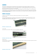
DDR4 DDR4-Speicher (Double Data Rate der vierten Generation) ist der schnellere Nachfolger der DDR2- und DDR3-Technologie und ermöglicht bis zu 512 GB Kapazität im Vergleich zu der maximalen Kapazität von 128 GB pro DIMM beim DDR3-Speicher. Synchroner DDR4-Speicher (Dynamic Random-Access) ist mit einer anderen Passung versehen als SDRAM und DDR. Damit soll verhindert werden, dass Benutzer den falschen Typ Speicher im System installieren. DDR4 benötigt 20 Prozent weniger Volt bzw.
Speicherfehler Bei Speicherfehlern auf dem System wird der neue ON-FLASH-FLASH- oder ON-FLASH-ON-Fehlercode angezeigt. Wenn alle Speicher ausfallen, lässt sich das LCD-Display nicht einschalten. Beheben Sie mögliche Speicherfehler, indem Sie funktionierende Speichermodule in Speicheranschlüssen an der Unterseite des Systems oder unter der Tastatur ausprobieren, wie in einigen tragbaren Systemen.
Mit den heutigen steigenden Anforderungen an Datenübertragungen mit High-Definition-Videoinhalten, Terabyte-Speichergeräten, digitalen Kameras mit hoher Megapixelanzahl usw. ist USB 2.0 möglicherweise nicht schnell genug. Darüber hinaus kam kein USB 2.0Anschluss jemals in die Nähe des theoretischen maximalen Durchsatzes von 480 Mbit/s mit einer Datenübertragung von etwa 320 Mbit/s (40 MB/s) – das ist der tatsächliche reale Höchstwert. Entsprechend werden die USB 3.0 /USB-3.
Abwechselnder Modus USB-Typ C ist ein neuer, extrem kleiner Anschlussstandard. Er ist um zwei Drittel kleiner als der ältere USB-Typ-A-Anschluss. Es handelt sich um einen einzelnen Anschlussstandard, der mit jeder Art von Gerät kompatibel sein sollte. USB-Typ-C-Ports können unter Verwendung von „alternativen Modi“ eine Vielzahl verschiedener Protokolle unterstützen, wodurch über Adapter HDMI-, VGA-, DisplayPort-, oder andere Arten von Verbindungen von diesem einzelnen USB-Port ausgegeben werden können.
1. 2. 3. 4. Thunderbolt 3 verwendet USB-Typ-C-Stecker und -Kabel. Es ist kompakt und reversibel. Thunderbolt 3 unterstützt Geschwindigkeiten von bis zu 40 Gbps. DisplayPort 1.4 – kompatibel mit vorhandenen DisplayPort-Monitoren, -Geräten und -Kabeln Stromversorgung über USB – Bis zu 130 W auf unterstützten Computern Hauptmerkmale von Thunderbolt 3 über USB Typ-C 1. Thunderbolt, USB, DisplayPort und Stromversorgung über USB-Typ-C in einem einzelnen Kabel (Merkmale können je nach Produkt variieren). 2.
Vorteile von HDMI • • • • • Qualitäts-HDMI überträgt unkomprimiertes digitales Audio und Video bei höchster, gestochen scharfer Bildqualität. Kostengünstige HDMI bietet die Qualität und Funktionalität einer digitalen Schnittstelle, während sie auch unkomprimierte Videoformate in einer einfachen, kosteneffektiven Weise unterstützt.
3 Hauptkomponenten Ihres Systems 1. Seitenabdeckung 2.
3. 4. 5. 6. 7. 8. 9. 10. 11. 12. 13. 14. 15. 16. Festplatte Festplattenhalterung Festplatte und optisches Laufwerksmodul Optisches Laufwerk Betriebsschalter Systemplatine E/A-Platine Seitenabdeckung Systemlüfter Lautsprecher Arbeitsspeichermodul Prozessor Netzteil Grafikkarte ANMERKUNG: Dell stellt eine Liste der Komponenten und ihrer Artikelnummern für die ursprüngliche erworbene Systemkonfiguration bereit. Diese Teile sind gemäß den vom Kunden erworbenen Garantieleistungen verfügbar.
4 Entfernen und Einbauen von Komponenten Themen: • • • • • • • • • • • • • • • • • • • • • • • • • Empfohlene Werkzeuge Liste der Schraubengrößen Layout der Hauptplatine Seitenabdeckung Erweiterungskarte Knopfzellenbatterie Festplattenbaugruppe Frontverkleidung Festplatte und optisches Laufwerksmodul Optisches Laufwerk Speichermodul Kühlkörper und Lüfter Eingriffschalter Netzschalter Prozessor M.
Liste der Schraubengrößen Tabelle 4. Liste der Schraubengrößen Komponente #6,32x1,4 #6-32 M3x6 Systemplatine 5 1 1 Schraubenmutter der SSD-Karte M3x5 M3x3 M2x3.
Layout der Hauptplatine 1. PCI-e x16-Anschluss (Steckplatz 2) 3. USB-Typ-C-Stecker 5. Anschluss des Eingriffsschalters (Intruder) 7. Prozessorsockel (CPU) 9. Speichersteckplätze (DIMM1, DIMM2, DIMM3, DIMM4) 11. Remote-Netzschalteranschluss 13. Anschluss für M.2-SSD-Karte/Intel Optane 15. Jumper zur Passwortlöschung (PASSWORD_CLR) 17. Netzteil-Anschluss 19. Anschluss für internen Lautsprecher (INT_SPKR) 21. Interner USB-Anschluss (FRONT_USB) 23. SATA 2-Anschluss 2.
Anbringen der Seitenabdeckung 1. Setzen Sie die Abdeckung auf das System und schieben Sie sie, bis sie einrastet. 2. Der Entriegelungsriegel verriegelt die Seitenabdeckung automatisch im System.
3. Folgen Sie den Anweisungen unter Nach der Arbeit an Komponenten im Inneren des Computers. Erweiterungskarte Entfernen der Erweiterungskarte 1. Folgen Sie den Anweisungen unter Vor der Arbeit an Komponenten im Inneren des Computers. 2. Entfernen Sie die Seitenabdeckung. 3. So entfernen Sie die Erweiterungskarte: a) Ziehen Sie an der Metalllasche, um die Verriegelung der Erweiterungskarte zu öffnen [1]. b) Ziehen Sie an der Freigabelasche an der Unterseite der Erweiterungskarte [2].
Installieren der Erweiterungskarte 1. Setzen Sie die Erweiterungskarte in den Anschluss auf der Systemplatine ein. 2. Drücken Sie die Erweiterungskarte, bis sie einrastet [1]. 3. Schließen Sie die Verriegelung der Erweiterungskarte und drücken Sie darauf, bis sie einrastet [2].
4. Bringen Sie die Seitenabdeckung an. 5. Folgen Sie den Anweisungen unter Nach der Arbeit an Komponenten im Inneren des Computers. Knopfzellenbatterie Entfernen der Knopfzellenbatterie 1. Folgen Sie den Anweisungen unter Vor der Arbeit an Komponenten im Inneren des Computers. 2. Entfernen Sie die Seitenabdeckung. 3. So entfernen Sie die Knopfzellenbatterie: a) Drücken Sie den Entriegelungsriegel mit einem Kunststoffstift, bis die Knopfzellenbatterie herausspringt [1].
Einsetzen der Knopfzellenbatterie 1. Setzen Sie die Knopfzellenbatterie in den entsprechenden Steckplatz auf der Systemplatine ein [1]. 2. Drücken Sie die Batterie in den Anschluss, bis sie einrastet [2].
3. Bringen Sie die Seitenabdeckung an. 4. Folgen Sie den Anweisungen unter Nach der Arbeit an Komponenten im Inneren des Computers. Festplattenbaugruppe Entfernen der Festplattenbaugruppe 1. Folgen Sie den Anweisungen unter Vor der Arbeit an Komponenten im Inneren des Computers. 2. Entfernen Sie die Seitenabdeckung. 3. So entfernen Sie die Festplattenbaugruppe: a) Trennen Sie das Datenkabel der Festplatte und das Stromkabel von den Anschlüssen an der Festplatte [1, 2].
4. So entfernen Sie die 2,5-Zoll-Festplatte aus der Baugruppenhalterung: a) Ziehen Sie an einer Seite der Festplattenhalterung, um die Haltestifte auf der Halterung aus den Steckplätzen an der Festplatte zu lösen [1,2]. b) Heben Sie die Festplatte aus der Festplattenhalterung heraus [3]. 5. So entfernen Sie die 3,5-Zoll-Festplatte aus der Baugruppenhalterung: a) Ziehen Sie an einer Seite der Festplattenhalterung, um die Haltestifte auf der Halterung aus den Steckplätzen an der Festplatte zu lösen [1,2].
Einbauen der Festplattenbaugruppe 1. So bauen Sie die 2,5-Zoll-Festplatte in die Baugruppenhalterung ein: a) Richten Sie die Laschen an der Festplatte an den Steckplätzen an der Festplattenbaugruppe in einem Winkel von 30° aus [1]. b) Drücken Sie die Festplatte, bis sie in der Halterung der Festplattenbaugruppe fest sitzt [2]. 2.
4. Bringen Sie die Seitenabdeckung an. 5. Folgen Sie den Anweisungen unter Nach der Arbeit an Komponenten im Inneren des Computers. Frontverkleidung Entfernen der Frontverkleidung 1. Befolgen Sie die Anweisungen im Abschnitt Vor der Arbeit an Komponenten im Inneren des Computers. 2. Entfernen Sie die Seitenabdeckung. 3.
Installieren der Frontverkleidung 1. Richten Sie die Blende aus und setzen Sie die Halteklammern auf der Blende in die Steckplätze im System ein. 2. Drücken Sie auf die Blende, bis die Laschen einrasten. 3. Bringen Sie die Seitenabdeckung an. 4. Folgen Sie den Anweisungen unter Nach der Arbeit an Komponenten im Inneren des Computers.
Festplatte und optisches Laufwerksmodul Entfernen der Festplatte und des optischen Laufwerksmoduls 1. Folgen Sie den Anweisungen unter Vor der Arbeit an Komponenten im Inneren des Computers. 2. Entfernen Sie folgende Komponenten: a) Seitenabdeckung b) Frontblende 3. So lösen Sie die Festplatte und das optische Laufwerkmodul: a) Trennen Sie das Datenkabel der Festplatte und das Stromkabel von den Anschlüssen an der Festplatte [1, 2].
4. So entfernen Sie die Festplatte und das optische Laufwerkmodul: a) Trennen Sie das Datenkabel des optischen Laufwerks und das Stromkabel des optischen Laufwerks von den Anschlüssen am optischen Laufwerk [1, 2]. b) Schieben Sie die Festplatte und das optische Laufwerkmodul und heben Sie beide Komponenten aus dem System [3].
Einbauen der Festplatte und des optischen Laufwerksmoduls 1. Setzen Sie die Laschen an der Festplatte und am optischen Laufwerksmodul in einem Winkel von 30° in den Steckplatz am System ein [1]. 2. Verbinden Sie das Datenkabel des optischen Laufwerks und das Stromkabel mit den Anschlüssen am optischen Laufwerk [2, 3]. 3. Senken Sie die Festplatte und das optische Laufwerksmodul ab, bis beide Komponenten im entsprechenden Steckplatz einrasten [4].
4. Führen Sie das Datenkabel des optischen Laufwerks und das Stromkabel durch die Halteklammern [1]. 5. Führen Sie das Datenkabel der Festplatte und die Stromkabel durch die Freigabelasche des HDD und des ODD [2].
6. Schieben Sie die Freigabelasche, um das Modul zu sperren [1]. 7. Verbinden Sie das Datenkabel der Festplatte und das Stromkabel mit den Anschlüssen an der Festplatte [2, 3].
8. Bauen Sie folgende Komponenten ein: a) Frontblende b) Seitenabdeckung 9. Folgen Sie den Anweisungen unter Nach der Arbeit an Komponenten im Inneren des Computers. Optisches Laufwerk Entfernen des optischen Laufwerks 1. Folgen Sie den Anweisungen unter Vor der Arbeit an Komponenten im Inneren des Computers. 2. Entfernen Sie folgende Komponenten: a) Seitenabdeckung b) Frontblende 3.
d) Trennen Sie das Datenkabel des optischen Laufwerks und das Stromkabel des optischen Laufwerks von den Anschlüssen auf dem optischen Laufwerk [1, 2] und senken Sie die Festplatte und das optische Modul ab, bis beide Komponenten fest sitzen [3].
e) Drücken und schieben Sie den Entriegelungsriegel am optischen Laufwerk [1, 2] und ziehen Sie das optische Laufwerk aus dem System heraus [3].
Installieren des optischen Laufwerks 1. Schieben Sie das optische Laufwerk in den entsprechenden Steckplatz im System [1]. 2. Heben Sie die Festplatte und das optische Modul an [2].
3. Verbinden Sie das Datenkabel des optischen Laufwerks und das Stromkabel mit den Anschlüssen am optischen Laufwerk [1, 2]. 4. Setzen Sie die Festplatte und das optische Modul zurück auf das System [3].
5. Verbinden Sie das Datenkabel der Festplatte und das Stromkabel der Festplatte mit den Anschlüssen an der Festplatte [1, 2]. 6. Schieben Sie die Freigabelasche, um das Modul zu sperren [3,4].
7. Bauen Sie folgende Komponenten ein: a) Frontblende b) Seitenabdeckung 8. Folgen Sie den Anweisungen unter Nach der Arbeit an Komponenten im Inneren des Computers. Speichermodul Entfernen des Speichermoduls 1. Folgen Sie den Anweisungen unter Vor der Arbeit an Komponenten im Inneren des Computers. 2. Entfernen Sie folgende Komponenten: a) Seitenabdeckung b) Frontblende c) Festplatten- und optisches Laufwerksmodul 3.
Einsetzen des Speichermoduls 1. Richten Sie die Kerbe am Speichermodul an der Lasche des Speichermodul-Anschlusses aus. 2. Setzen Sie das Speichermodul in den Speichermodulsockel ein [1]. 3. Drücken Sie auf das Speichermodul, bis die Speichermodul-Halteklammern einrasten [2].
4. Bauen Sie folgende Komponenten ein: a) Festplatte und optisches Laufwerksmodul b) Frontblende c) Seitenabdeckung 5. Folgen Sie den Anweisungen unter Nach der Arbeit an Komponenten im Inneren des Computers. Kühlkörper und Lüfter Entfernen des Kühlkörpers und des Kühlkörperlüfters 1. Folgen Sie den Anweisungen unter Vor der Arbeit an Komponenten im Inneren des Computers. 2. Entfernen Sie folgende Komponenten: a) Seitenabdeckung b) Frontblende c) Festplatten- und optisches Laufwerksmodul 3.
4. So entfernen Sie den Kühlkörperlüfter: a) Entfernen Sie die vier Schrauben vom Lüfter und heben Sie den Lüfter vom Kühlkörper ab. Installieren des Kühlkörpers und des Kühlkörperlüfters 1. So installieren Sie den Kühlkörperlüfter: a) Richten Sie die Steckplätze am Lüfter an den Steckplätzen am Kühlkörpermodul aus und setzten Sie sie ein. b) Bringen Sie die vier Schrauben wieder an, mit denen der Kühlkörperlüfter am Kühlkörper befestigt ist.
2. So setzen Sie den Kühlkörper ein: a) Richten Sie den Kühlkörper am Prozessor aus [1]. b) Ziehen Sie die vier unverlierbaren Schrauben fest, um die Kühlkörperbaugruppe an der Systemplatine zu befestigen [2]. ANMERKUNG: Ziehen Sie die Schrauben in der auf der Systemplatine angegebenen Reihenfolge (1,2,3,4) fest. c) Verbinden Sie das Kabel des Kühlkörperlüfters mit dem Steckplatz auf der Systemplatine [3]. 3.
4. Folgen Sie den Anweisungen unter Nach der Arbeit an Komponenten im Inneren des Computers. Eingriffschalter Entfernen des Eingriffsschalters 1. Folgen Sie den Anweisungen unter Vor der Arbeit an Komponenten im Inneren des Computers. 2. Entfernen Sie folgende Komponenten: a) b) c) d) Seitenabdeckung Frontblende Festplatten- und optisches Laufwerksmodul Kühlkörper und Kühlkörperlüfter 3.
3. Bauen Sie folgende Komponenten ein: a) b) c) d) Kühlkörper und des Kühlkörperlüfter Festplatte und optisches Laufwerksmodul Frontblende Seitenabdeckung 4. Folgen Sie den Anweisungen unter Nach der Arbeit an Komponenten im Inneren des Computers. Netzschalter Entfernen des Netzschalters 1. Folgen Sie den Anweisungen unter Vor der Arbeit an Komponenten im Inneren des Computers. 2. Entfernen Sie folgende Komponenten: a) Seitenabdeckung b) Frontblende c) Festplatten- und optisches Laufwerksmodul 3.
Einbauen des Betriebsschalters 1. Setzen Sie das Netzschaltermodul in den Steckplatz am Gehäuse ein und drücken Sie darauf, bis es mit einem Klick einrastet [1]. 2. Verbinden Sie das Netzschalterkabel mit dem Anschluss auf der Systemplatine [2].
3. Bauen Sie folgende Komponenten ein: a) Festplatte und optisches Laufwerksmodul b) Frontblende c) Seitenabdeckung 4. Folgen Sie den Anweisungen unter Nach der Arbeit an Komponenten im Inneren des Computers. Prozessor Entfernen des Prozessors 1. Folgen Sie den Anweisungen unter Vor der Arbeit an Komponenten im Inneren des Computers. 2. Entfernen Sie folgende Komponenten: a) b) c) d) Seitenabdeckung Frontblende Festplatten- und optisches Laufwerksmodul Kühlkörper und Kühlkörperlüfter 3.
Einbauen des Prozessors 1. Setzen Sie den Prozessor so in den Sockel, dass die Steckplätze am Prozessor an den Sockelpassungen ausgerichtet sind [1]. 2. Schließen Sie die Prozessorabdeckung, indem Sie sie unter die Verschlussschraube schieben [2]. 3. Senken Sie den Sockelhebel und drücken Sie ihn unter die Lasche, um ihn zu verriegeln [3].
4. Bauen Sie folgende Komponenten ein: a) b) c) d) Kühlkörper und des Kühlkörperlüfter Festplatte und optisches Laufwerksmodul Frontblende Seitenabdeckung 5. Folgen Sie den Anweisungen unter Nach der Arbeit an Komponenten im Inneren des Computers. M.2-PCIe-Solid-State-Laufwerk (SSD) Entfernen des M.2-PCIe-SSD-Laufwerks 1. Folgen Sie den Anweisungen unter Vor der Arbeit an Komponenten im Inneren des Computers. 2.
ANMERKUNG: M.2-PCIe-SSDs mit einer Kapazität von über 512 GB (512 GB/1 TB/2 TB) müssen mit einer Wärmefalle installiert werden. Für M.2-SATA-SSDs oder M.2-PCIe-SSDs mit 128 GB und 256 GB ist keine Wärmefalle erforderlich. Installieren des M.2-PCIe-SSD-Laufwerks 1. Setzen Sie die Wärmefalle in den Steckplatz auf der Systemplatine ein [1]. ANMERKUNG: M.2-PCIe-SSDs mit einer Kapazität von über 512 GB (512 GB/1 TB/2 TB) müssen mit einer Wärmefalle installiert werden. Für M.2-SATA-SSDs oder M.
4. Bauen Sie folgende Komponenten ein: a) Festplatte und optisches Laufwerksmodul b) Frontblende c) Seitenabdeckung 5. Folgen Sie den Anweisungen unter Nach der Arbeit an Komponenten im Inneren des Computers. Intel Optane-Karte Entfernen der Intel Optane-Karte 1. Folgen Sie den Anweisungen unter Vor der Arbeit an Komponenten im Inneren des Computers. 2. Entfernen Sie folgende Komponenten: a) Seitenabdeckung b) Frontblende c) Festplatten- und optisches Laufwerksmodul 3.
Einsetzen der Intel Optane-Karte 1. Setzen Sie die Wärmefalle in den Steckplatz auf der Systemplatine ein [1]. 2. Setzen Sie die Intel Optane-Karte in den Kartensteckplatz auf der Systemplatine ein [2]. 3. Bringen Sie die Schraube (M2x3,5) zur Befestigung der Intel Optane-Karte an der Systemplatine wieder an [3]. ANMERKUNG: Intel Optane-Module müssen mit einer Wärmefalle installiert werden.
4. Bauen Sie folgende Komponenten ein: a) Festplatten- und optisches Laufwerksmodul b) Frontblende c) Seitenabdeckung 5. Folgen Sie den Anweisungen unter Nach der Arbeit an Komponenten im Inneren des Computers. SD-Kartenleser (optional) Entfernen des SD-Kartenlesers 1. Folgen Sie den Anweisungen unter Vor der Arbeit an Komponenten im Inneren des Computers. 2. Entfernen Sie folgende Komponenten: a) Seitenabdeckung b) Frontblende c) Festplatten- und optisches Laufwerksmodul 3.
c) Heben Sie den SD-Kartenleser aus dem Steckplatz auf der Systemplatine [3]. Einbauen des SD-Kartenlesers 1. Führen Sie die Stromkabel wieder durch die Halteklammer am SD-Kartenleser [1]. 2. Setzen Sie den SD-Kartenleser in den Steckplatz auf der Systemplatine ein [2]. 3. Bringen Sie die zwei M3-Schrauben wieder an, mit denen der SD-Kartenleser an der E/A-Leiste und an der Systemplatine befestigt wird [3].
4. Bauen Sie folgende Komponenten ein: a) Festplatte und optisches Laufwerksmodul b) Frontblende c) Seitenabdeckung 5. Folgen Sie den Anweisungen unter Nach der Arbeit an Komponenten im Inneren des Computers. Interne Antenne (optional) Entfernen der internen Antenne 1. Folgen Sie den Anweisungen unter Vor der Arbeit an Komponenten im Inneren des Computers. 2. Entfernen Sie folgende Komponenten: a) Seitenabdeckung b) Frontblende c) Festplatten- und optisches Laufwerksmodul 3.
c) Entfernen Sie die Schraube, mit der die Antenne am Gehäuse befestigt ist [1]. d) Lösen Sie das schwarze Antennenkabel von dem ANT-B-Steckplatz auf dem Gehäuse [2, 3].
e) Entfernen Sie die Schraube, mit der die Antenne am Gehäuse befestigt ist [1]. f) Lösen Sie das weiße Antennenkabel von dem ANT-W-Steckplatz auf dem Gehäuse [2, 3].
Einbauen der internen Antenne 1. Ziehen Sie das Mylar-Klebeband von der internen Antenne ab.
2. So bauen Sie die Antenne in das System ein: a) Richten Sie das weiße Antennenkabel an dem ANT-W-Steckplatz auf dem Gehäuse aus und setzen Sie es ein [1, 2]. b) Bringen Sie die Schraube wieder an, mit der die Antenne am Gehäuse befestigt wird [3].
c) Richten Sie das schwarze Antennenkabel an dem ANT-B-Steckplatz auf dem Gehäuse aus und setzen Sie es ein [1, 2]. d) Bringen Sie die Schraube wieder an, mit der die Antenne am Gehäuse befestigt wird [3].
e) Führen Sie das Antennenkabel über die zwei Haken [1]. f) Führen Sie das Antennenkabel durch die Kabelführung am Gehäuse [2].
g) Entfernen Sie die Kabelführung aus Kunststoff vom Kabel der internen Antenne.
3. Bauen Sie folgende Komponenten ein: a) Festplatte und optisches Laufwerksmodul b) Frontblende c) Seitenabdeckung 4. Folgen Sie den Anweisungen unter Nach der Arbeit an Komponenten im Inneren des Computers. Externe Antenne – optional Entfernen der externen Antenne 1. Folgen Sie den Anweisungen unter Vor der Arbeit an Komponenten im Inneren des Computers. 2. Entfernen Sie folgende Komponenten: a) Seitenabdeckung b) Frontblende c) Festplatten- und optisches Laufwerksmodul 3.
b) Lösen Sie das Antennenkabel aus der Halteklemme auf dem Gehäuse [1]. c) Entfernen Sie die Halteklemme aus dem Gehäuse [2].
d) e) f) g) Trennen Sie die Antennenanschlüsse von den Anschlüssen auf der WLAN-Karte. Entfernen Sie die Schraubenmuttern, mit denen die Antennenanschlüsse am Gehäuse befestigt sind [1]. Entfernen Sie die Unterlegscheiben aus Metall an den Antennenanschlüssen [2]. Entfernen Sie die Antennenkabel aus dem Antennensteckplatz am Gehäuse [3].
Einbauen der externen Antenne 1.
2. So bauen Sie die Antenne in das System ein: a) Entfernen Sie die Abdeckungen vom Antennenkabel [1]. b) Lösen und entfernen Sie die Schraubenmutter [2]. c) Entfernen Sie die metallische Unterlegscheibe [3]. d) Drücken Sie den Platzhalter mit einem Schraubenzieher.
e) Schieben Sie die Antennenkabel in den Antennensteckplatz am Gehäuse [1]. f) Bringen Sie die Unterlegscheiben aus Metall an den Antennenanschlüssen wieder an [2]. g) Bringen Sie die Schraubenmuttern wieder an, mit denen die Antennenanschlüsse am Gehäuse befestigt werden [3].
h) Befestigen Sie die Halteklemme am Gehäuse wie in der Abbildung gezeigt [1]. i) Führen Sie das Antennenkabel durch die Halteklemme [2]. j) Ziehen Sie die Isolierung aus den Antennenkabelanschlüssen heraus [3].
k) Verbinden Sie die Antennenanschlüsse mit den Anschlüssen auf der WLAN-Karte. l) Ziehen Sie die Antenne mit den Schrauben des Antennenkabelanschlusses an.
3. Bauen Sie folgende Komponenten ein: a) Festplatte und optisches Laufwerksmodul b) Frontblende c) Seitenabdeckung 4. Folgen Sie den Anweisungen unter Nach der Arbeit an Komponenten im Inneren des Computers. M.2-2230-WLAN-Karte (optional) Entfernen der M.2-2230-WLAN-Karte 1. Folgen Sie den Anweisungen unter Vor der Arbeit an Komponenten im Inneren des Computers. 2. Entfernen Sie folgende Komponenten: a) Seitenabdeckung b) Frontblende c) Festplatten- und optisches Laufwerksmodul 3. So entfernen Sie die M.
Einsetzen der M.2-2230-WLAN-Karte 1. So setzen Sie die M.2-2230-WLAN-Karte ein: a) b) c) d) 74 Richten Sie die WLAN-Karte am Steckplatz für WLAN-Karten aus und setzen Sie sie ein [1]. Schließen Sie die Antennenkabel an der WLAN-Karte an [2]. Setzen Sie die WLAN-Kartenhalterung auf der WLAN-Karte ein [3]. Bringen Sie die M2-Schraube wieder an, mit der die WLAN-Kartenhalterung und die WLAN-Karte an der Systemplatine befestigt werden [4].
2. Bauen Sie folgende Komponenten ein: a) Festplatte und optisches Laufwerksmodul b) Frontblende c) Seitenabdeckung 3. Folgen Sie den Anweisungen unter Nach der Arbeit an Komponenten im Inneren des Computers. Netzteil Entfernen des Netzteils 1. Folgen Sie den Anweisungen unter Vor der Arbeit an Komponenten im Inneren des Computers. 2. Entfernen Sie folgende Komponenten: a) Seitenabdeckung b) Frontblende c) Festplatten- und optisches Laufwerksmodul 3.
4. So entfernen Sie das Netzteil: a) Entfernen Sie die drei Schrauben, mit denen das Netzteil am System befestigt ist [1]. b) Drücken Sie auf die blaue Freigabelasche [4] am hinteren Ende des Netzteils, schieben Sie das Netzteil und heben Sie es aus dem System [2].
Installieren des Netzteils 1. Setzen Sie das Netzteil in das Gehäuse ein und schieben Sie es in Richtung der Rückseite des Systems, um es zu befestigen [1]. 2. Bringen Sie die Schrauben wieder an, mit denen das Netzteil an der Rückseite des Systemgehäuses befestigt wird.
3. Verbinden Sie das Stromkabel mit dem Anschluss auf der Systemplatine [1]. 4. Führen Sie das Stromkabel des Systems durch die Halteklammern [2]. 5. Führen Sie das CPU-Stromkabel durch die Halteklammern [3]. 6. Verbinden Sie das CPU-Stromkabel mit dem Anschluss auf der Systemplatine [4].
7. Bauen Sie folgende Komponenten ein: a) Festplatte und optisches Laufwerksmodul b) Frontblende c) Seitenabdeckung 8. Folgen Sie den Anweisungen unter Nach der Arbeit an Komponenten im Inneren des Computers. Lautsprecher Entfernen des Lautsprechers 1. Folgen Sie den Anweisungen unter Vor der Arbeit an Komponenten im Inneren des Computers. 2. Entfernen Sie folgende Komponenten: a) Seitenabdeckung b) Frontblende c) Festplatten- und optisches Laufwerksmodul 3.
Einbauen des Lautsprechers 1. Setzen Sie den Lautsprecher in den Steckplatz auf dem Systemgehäuse ein und drücken Sie ihn an, bis er einrastet [1]. 2. Schließen Sie das Lautsprecherkabel wieder an den Anschluss an der Systemplatine an [2].
3. Bauen Sie folgende Komponenten ein: a) Festplatte und optisches Laufwerksmodul b) Frontblende c) Seitenabdeckung 4. Folgen Sie den Anweisungen unter Nach der Arbeit an Komponenten im Inneren des Computers. Systemlüfter Entfernen des Systemlüfters 1. Folgen Sie den Anweisungen unter Vor der Arbeit an Komponenten im Inneren des Computers. 2. Entfernen Sie folgende Komponenten: a) Seitenabdeckung b) Frontblende c) Festplatten- und optisches Laufwerksmodul 3.
Einbauen des Systemlüfters 1. So bauen Sie den Systemlüfter wieder ein: a) Richten Sie den Systemlüfter entsprechend aus und setzen Sie ihn in das Systemgehäuse ein [1]. b) Schieben Sie die Gummidichtungen durch das Gehäuse und schieben Sie sie entlang der Aussparung, um sie zu befestigen [2, 3]. c) Verbinden Sie das Systemlüfterkabel mit der Systemplatine [4].
2. Bauen Sie folgende Komponenten ein: a) Festplatte und optisches Laufwerksmodul b) Frontblende c) Seitenabdeckung 3. Folgen Sie den Anweisungen unter Nach der Arbeit an Komponenten im Inneren des Computers. Systemplatine Entfernen der Systemplatine 1. Folgen Sie den Anweisungen unter Vor der Arbeit an Komponenten im Inneren des Computers. 2.
c) Trennen Sie das Kabel des Netzschalters [3], lösen Sie das Stromkabel aus den Halteklammern auf dem Gehäuse [4] und lösen Sie das Netzteilkabel [5] und das Kabel des Eingriffsschalters [6] von den Anschlüssen auf der Systemplatine. 4. Trennen Sie das Kabel des Eingriffsschalters [1], das Netzteilkabel [2], das Datenkabel [3], das Kabel des Systemlüfters [4], das SATAKabel [5] und das SATA-Stromkabel [6].
5. So entfernen Sie die Schrauben von der Systemplatine: a) Entfernen Sie die einzelne Abstandsschraube (#6-32) und die einzelne M3x6-Schraube, mit denen die Systemplatine am System befestigt ist [1,2]. b) Entfernen Sie die fünf Schrauben, mit denen die Systemplatine am Gehäuse befestigt ist [3].
6. So entfernen Sie die Systemplatine: a) Heben und schieben Sie die Systemplatine aus dem System [1, 2].
Einbauen der Systemplatine 1. Fassen Sie die Systemplatine an den Rändern an und richten Sie sie zur Gehäuserückseite aus. 2. Senken Sie die Systemplatine in das Gehäuse ab, bis die Anschlüsse auf der Rückseite der Systemplatine an den Schlitzen in der Rückwand des Gehäuses und die Schraublöcher der Systemplatine an den Abstandshaltern des Gehäuses ausgerichtet sind [1,2]. 3.
4.
5. Setzen Sie den Haken auf der E/A-Leiste in den Schlitz am Gehäuse ein und drehen Sie E/A-Leiste, um sie zu schließen [1]. 6. Befestigen Sie die E/A-Leiste mit der Schraube am Gehäuse [2]. 7. Schließen Sie das Kabel des Netzschalters [3] an, führen Sie das Stromkabel durch die Halteklammern auf dem Gehäuse [4] und schließen Sie das Netzteilkabel [5] und das Kabel des Eingriffsschalters [6] an die Anschlüsse auf der Systemplatine an.
8. Bauen Sie folgende Komponenten ein: a) b) c) d) e) f) g) h) i) j) M.2-2230-WLAN-Karte SD-Kartenlesegerät Intel Optane-Karte M.2-PCIe-SSD-Karte Speichermodul Prozessor Kühlkörper und Kühlkörperlüfter Festplatten- und optisches Laufwerksmodul Frontblende Seitenabdeckung 9. Folgen Sie den Anweisungen unter Nach der Arbeit an Komponenten im Inneren des Computers.
5 Problembehandlung für Ihren Computer Enhanced Pre-boot System Assessment – ePSADiagnose Die ePSA-Diagnose (auch als Systemdiagnose bezeichnet) führt eine komplette Prüfung der Hardware durch. Die ePSA-Diagnose ist in das BIOS integriert und wird intern vom BIOS gestartet.
Die folgende Tabelle zeigt die verschiedenen Anzeigemuster und was diese angeben. Tabelle 5.
Gelbe LED-Zustandsanzeige Weiße LED-Zustandsanzeige Systemzustand Anmerkungen Konfiguration oder Fehler. BIOS eliminiert 0101-Videocode. 3 2 BIOS-Zustand 5 BIOS-POST-Code (Altes LEDMuster 0110) Kombination von Speicher und USB-Konfiguration oder Fehler. BIOS eliminiert 0111USB-Code. 3 3 BIOS-Zustand 6 BIOS-POST-Code (Altes LEDMuster 1000) MEMKonfiguration, kein Speicher erkannt. 3 4 BIOS-Zustand 7 BIOS-POST-Code (Altes LEDMuster 1001) Schwerwiegender Fehler der Hauptplatine.
Fehlermeldungen Beschreibung ERROR READING PCMCIA CARD Der Computer kann die ExpressCard nicht erkennen. Setzen Sie die Karte neu ein oder verwenden Sie eine andere Karte. EXTENDED MEMORY SIZE HAS CHANGED Die im NVRAM (nichtflüchtiger Speicher) verzeichnete Speichergröße stimmt nicht mit dem im Computer installierten Speichermodul überein. Den Computer neu starten. Wenn der Fehler erneut auftritt, wenden Sie sich an Dell.
Fehlermeldungen Beschreibung nach der Installation eines Speichermoduls angezeigt. Korrigieren Sie die entsprechenden Optionen im System-Setup-Programm. KEYBOARD CLOCK LINE FAILURE Überprüfen Sie bei einer externen Tastatur die Kabelverbindung. Führen Sie den Tastatur-Controller-Test (Keyboard ControllerTest) von Dell Diagnostics aus. KEYBOARD CONTROLLER FAILURE Überprüfen Sie bei einer externen Tastatur die Kabelverbindung.
Fehlermeldungen Beschreibung SECTOR NOT FOUND Das Betriebssystem kann einen Sektor auf der Festplatte nicht finden. Entweder ist ein Sektor defekt oder die Dateizuweisungstabelle (File Allocation Table, FAT) auf der Festplatte ist beschädigt. Führen Sie das Fehlerprüfprogramm von Windows aus, um die Dateistruktur auf der Festplatte zu überprüfen. Eine entsprechende Anleitung finden Sie in Windows Help and Support (klicken Sie zu diesem Zwecke auf Start > Help and Support.
Systemmeldung Beschreibung Hard-disk drive failure Möglicher Festplattenfehler beim POST. Keyboard failure Tastaturfehler oder loses Kabel. Wenn das Problem durch erneutes festes Anschließen des Kabels nicht behoben wird, tauschen Sie die Tastatur aus. No boot device available Auf der Festplatte ist keine startfähige Partition vorhanden, das Festplattenkabel ist nicht richtig angeschlossen, oder es ist kein startfähiges Gerät vorhanden.
6 Wie Sie Hilfe bekommen Themen: • Kontaktaufnahme mit Dell Kontaktaufnahme mit Dell ANMERKUNG: Wenn Sie nicht über eine aktive Internetverbindung verfügen, können Sie Kontaktinformationen auch auf Ihrer Auftragsbestätigung, dem Lieferschein, der Rechnung oder im Dell-Produktkatalog finden. Dell stellt verschiedene onlinebasierte und telefonische Support- und Serviceoptionen bereit.
A Staubfilter für Dell Precision 3431 Small Form Factor Der Staubfilter für Dell Precision 3431 Small Form Factor schützt das System vor Feinstaubpartikeln. Nach Einsetzen des Staubfilters kann das BIOS auf Grundlage des festgelegten Zeitintervalls so konfiguriert werden, dass vor Hochfahren des Systems eine Erinnerung zum Reinigen und Austauschen des Staubfilters generiert wird. Führen Sie die folgenden Schritte aus, um den Staubfilter einzusetzen: 1.
3. Starten Sie das System neu und drücken Sie F2, um das BIOS-Setupmenü aufzurufen. 4. Navigieren Sie im BIOS-Setupmenü zu System Configuration > Dust Filter Maintenance und wählen Sie einen der folgenden Intervalle aus: 15, 30, 60, 90, 120, 150 oder 180 Tage. ANMERKUNG: Standardeinstellung: Deaktiviert ANMERKUNG: Warnungen werden nur während eines Systemneustarts generiert, nicht während der normalen Betriebssystemausführung.
B Einbauen der USB-Type-C-Karte 1. Befolgen Sie die Anweisungen im Abschnitt Vor der Arbeit an Komponenten im Inneren des Computers. 2. Entfernen Sie die Seitenabdeckung: a) Schieben Sie den Entriegelungsriegel auf der Rückseite des Systems, bis er mit einem Klicken die Seitenabdeckung entsperrt [1]. b) Schieben und heben Sie die Seitenabdeckung aus dem System [2]. 3.
4. Lösen Sie die Festplatte und das optische Laufwerkmodul: a) Trennen Sie das Datenkabel der Festplatte und das Stromkabel von den Anschlüssen an der Festplatte [1, 2]. b) Schieben Sie die Freigabelasche, um die Festplatte und das optische Modul zu entsperren [3]. c) Lösen Sie die Festplattenkabel [1] und die Kabel des optischen Laufwerks [2] aus der Halteklammer und der Freigabelasche des HDD und ODD. d) Heben Sie die Festplatte und das optische Modul an [3].
5. Entfernen Sie die Festplatte und das optische Laufwerkmodul: a) Trennen Sie das Datenkabel des optischen Laufwerks und das Stromkabel des optischen Laufwerks von den Anschlüssen am optischen Laufwerk [1, 2]. b) Schieben Sie die Festplatte und das optische Laufwerkmodul und heben Sie beide Komponenten aus dem System [3].
6. Entfernen Sie den Kühlkörper mit dem Lüfter: a) Trennen Sie das Kabel des Kühlkörperlüfters von der Systemplatine [1]. b) Lösen Sie die vier unverlierbaren Schrauben, mit denen der Kühlkörper [2] befestigt ist, und heben Sie ihn aus dem System [3]. ANMERKUNG: Lösen Sie die Schrauben in der auf der Systemplatine angegebenen Reihenfolge (1,2,3,4).
7. So bauen Sie die USB-Type-C-Karte ein: a) Entfernen Sie die Blende mit einem Kreuzschlitzschraubendreher.
b) Schließen Sie das Kabel der USB-Type-C-Karte an den Anschluss auf der Systemplatine an [1]. c) Richten Sie die USB-Type-C-Karte entsprechend aus und setzen Sie sie in den Steckplatz am Systemgehäuse ein [2].
d) Schließen Sie das Kabel der USB-Type-C-Karte an den Anschluss auf der Systemplatine an [1]. e) Ziehen Sie die zwei Schrauben an, um die USB-Type-C-Karte am Systemgehäuse zu befestigen [2].
8. Installieren Sie den Kühlkörper: a) Richten Sie den Kühlkörper am Prozessor aus [1]. b) Ziehen Sie die vier unverlierbaren Schrauben fest, um die Kühlkörperbaugruppe an der Systemplatine zu befestigen [2]. ANMERKUNG: Ziehen Sie die Schrauben in sequenzieller Reihenfolge (1,2,3,4), wie auf der Systemplatine angegeben, fest. c) Verbinden Sie das Kabel des Kühlkörperlüfters mit dem Steckplatz auf der Systemplatine [3].
9. So bauen Sie die Festplatte und das optische Laufwerkmodul ein: a) Setzen Sie die Laschen an der Festplatte und am optischen Laufwerksmodul in einem Winkel von 30 ° in den Steckplatz am System ein [1]. b) Verbinden Sie das Datenkabel des optischen Laufwerks und das Stromkabel mit den Anschlüssen am optischen Laufwerk [2, 3]. c) Senken Sie die Festplatte und das optische Laufwerkmodul ab, bis beide Komponenten im entsprechenden Steckplatz einrasten [4].
d) Führen Sie das Datenkabel des optischen Laufwerks und das Stromkabel durch die Halteklammern [1]. e) Führen Sie das Datenkabel der Festplatte und die Stromkabel durch die Freigabelasche des HDD und des ODD [2].
f) Schieben Sie die Freigabelasche, um das Modul zu sperren [1]. g) Verbinden Sie das Datenkabel der Festplatte und das Stromkabel mit den Anschlüssen an der Festplatte [2, 3].
10. So bringen Sie die Frontblende an: a) Richten Sie die Blende aus und setzen Sie die Halteklammern auf der Blende in die Steckplätze im System. b) Drücken Sie auf die Blende, bis die Laschen einrasten.
11. So bringen Sie die Seitenabdeckung an: a) Setzen Sie die Abdeckung auf das System und schieben Sie sie, bis sie einrastet. b) Der Entriegelungsriegel verriegelt die Seitenabdeckung automatisch im System.
C Einsetzen der VGA-Karte 1. Befolgen Sie die Anweisungen im Abschnitt Vor der Arbeit an Komponenten im Inneren des Computers. 2. Entfernen Sie die Seitenabdeckung: a) Schieben Sie den Entriegelungsriegel auf der Rückseite des Systems, bis er mit einem Klicken die Seitenabdeckung entsperrt [1]. b) Schieben und heben Sie die Seitenabdeckung aus dem System [2]. 3.
4. Lösen Sie die Festplatte und das optische Laufwerkmodul: a) Trennen Sie das Datenkabel der Festplatte und das Stromkabel von den Anschlüssen an der Festplatte [1, 2]. b) Schieben Sie die Freigabelasche, um die Festplatte und das optische Modul zu entsperren [3]. c) Lösen Sie die Festplattenkabel [1] und die Kabel des optischen Laufwerks [2] aus der Halteklammer und der Freigabelasche des HDD und ODD. d) Heben Sie die Festplatte und das optische Modul an [3].
5. Entfernen Sie die Festplatte und das optische Laufwerkmodul: a) Trennen Sie das Datenkabel des optischen Laufwerks und das Stromkabel des optischen Laufwerks von den Anschlüssen am optischen Laufwerk [1, 2]. b) Schieben Sie die Festplatte und das optische Laufwerkmodul und heben Sie beide Komponenten aus dem System [3].
6. Entfernen Sie den Kühlkörper mit dem Lüfter: a) Trennen Sie das Kabel des Kühlkörperlüfters von der Systemplatine [1]. b) Lösen Sie die vier unverlierbaren Schrauben, mit denen der Kühlkörper [2] befestigt ist, und heben Sie ihn aus dem System [3]. ANMERKUNG: Lösen Sie die Schrauben in der auf der Systemplatine angegebenen Reihenfolge (1,2,3,4).
7. So installieren Sie die VGA-Karte: a) Entfernen Sie die Blende mit einem Kreuzschlitzschraubendreher.
b) Schließen Sie das VGA-Kartenkabel an den Anschluss auf der Systemplatine an [1]. c) Richten Sie die VGA-Karte entsprechend aus und setzen Sie sie in den Steckplatz am Systemgehäuse ein [2].
d) Ziehen Sie die zwei Schrauben an, um die VGA-Karte am Systemgehäuse zu befestigen [1].
8. Installieren Sie den Kühlkörper: a) Richten Sie den Kühlkörper am Prozessor aus [1]. b) Ziehen Sie die vier unverlierbaren Schrauben fest, um die Kühlkörperbaugruppe an der Systemplatine zu befestigen [2]. ANMERKUNG: Ziehen Sie die Schrauben in sequenzieller Reihenfolge (1,2,3,4), wie auf der Systemplatine angegeben, fest. c) Verbinden Sie das Kabel des Kühlkörperlüfters mit dem Steckplatz auf der Systemplatine [3].
9. So bauen Sie die Festplatte und das optische Laufwerkmodul ein: a) Setzen Sie die Laschen an der Festplatte und am optischen Laufwerksmodul in einem Winkel von 30 ° in den Steckplatz am System ein [1]. b) Verbinden Sie das Datenkabel des optischen Laufwerks und das Stromkabel mit den Anschlüssen am optischen Laufwerk [2, 3]. c) Senken Sie die Festplatte und das optische Laufwerkmodul ab, bis beide Komponenten im entsprechenden Steckplatz einrasten [4].
d) Führen Sie das Datenkabel des optischen Laufwerks und das Stromkabel durch die Halteklammern [1]. e) Führen Sie das Datenkabel der Festplatte und die Stromkabel durch die Freigabelasche des HDD und des ODD [2].
f) Schieben Sie die Freigabelasche, um das Modul zu sperren [1]. g) Verbinden Sie das Datenkabel der Festplatte und das Stromkabel mit den Anschlüssen an der Festplatte [2, 3].
10. So bringen Sie die Frontblende an: a) Richten Sie die Blende aus und setzen Sie die Halteklammern auf der Blende in die Steckplätze im System. b) Drücken Sie auf die Blende, bis die Laschen einrasten.
11. So bringen Sie die Seitenabdeckung an: a) Setzen Sie die Abdeckung auf das System und schieben Sie sie, bis sie einrastet. b) Der Entriegelungsriegel verriegelt die Seitenabdeckung automatisch im System.
D Kabelabdeckung für Dell Precision 3431 Small Form Factor Die Kabelabdeckung für Dell Precision 3431 Small Form Factor dient zum Schutz der Ports und der mit dem System verbundenen Kabel. Führen Sie die folgenden Schritte aus, um die Kabelabdeckung am Systemgehäuse anzubringen. ANMERKUNG: Die folgenden Abbildungen dienen lediglich der Veranschaulichung und können je nach Systemkonfiguration variieren. 1. Schieben Sie die Verriegelung vom Gehäuse weg, um die Kabelabdeckung zu lösen. 2.
5. Führen Sie die Kabel durch den Steckplatz der Kabelabdeckung [1] und schließen Sie sie an die entsprechenden Ports auf dem System an (2). Befestigen Sie das Kabel mit dem Kabelbinder und verriegeln Sie die Lasche [3]. Richten Sie die Haken aus Kunststoff auf der Kabelabdeckung an den Steckplätzen am System aus [4]. VORSICHT: Gehen Sie dabei vorsichtig vor, um die empfindlichen Haken aus Kunststoff nicht zu biegen oder zu brechen. 6.
ANMERKUNG: Verwenden Sie für mehr Sicherheit des Systems den halbringförmigen Bügel für ein Vorhängeschloss. 7. So entfernen Sie die Kabelabdeckung: a) Schieben Sie die Verriegelung vom Gehäuse weg, um die Kabelabdeckung zu lösen [1]. b) Heben Sie die Kabelabdeckung vom Systemgehäuse ab [2].