Precision 3630 Tower Service Manual 1 Regulatory Model: D24M Regulatory Type: D24M003 May 2020 Rev.
Notes, cautions, and warnings NOTE: A NOTE indicates important information that helps you make better use of your product. CAUTION: A CAUTION indicates either potential damage to hardware or loss of data and tells you how to avoid the problem. WARNING: A WARNING indicates a potential for property damage, personal injury, or death. © 2018 2020 Dell Inc. or its subsidiaries. All rights reserved. Dell, EMC, and other trademarks are trademarks of Dell Inc. or its subsidiaries.
Contents Chapter 1: Working on your computer........................................................................................... 6 Safety instructions.............................................................................................................................................................. 6 Turning off your computer — Windows 10...................................................................................................................6 Before working inside your computer....
Installing the speaker..................................................................................................................................................39 Coin cell battery................................................................................................................................................................. 41 Removing the coin cell battery.................................................................................................................................
Enhanced Pre-Boot System Assessment — ePSA diagnostics............................................................................ 94 Running the ePSA Diagnostics.................................................................................................................................94 Diagnostics..........................................................................................................................................................................94 Diagnostic error messages.........
1 Working on your computer Topics: • • • • Safety instructions Turning off your computer — Windows 10 Before working inside your computer After working inside your computer Safety instructions Use the following safety guidelines to protect your computer from potential damage and to ensure your personal safety. Unless otherwise noted, each procedure included in this document assumes that the following conditions exist: ● You have read the safety information that shipped with your computer.
NOTE: Ensure that the computer and all attached devices are turned off. If your computer and attached devices did not automatically turn off when you shut down your operating system, press and hold the power button for about 6 seconds to turn them off. Before working inside your computer To avoid damaging your computer, perform the following steps before you begin working inside the computer. 1. Ensure that you follow the Safety instructions. 2.
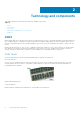
2 Technology and components This chapter details the technology and components available in the system. Topics: • • • • • DDR4 USB features USB Type-C Advantages of DisplayPort over USB Type-C HDMI 2.0 DDR4 DDR4 (double data rate fourth generation) memory is a higher-speed successor to the DDR2 and DDR3 technologies and allows up to 512 GB in capacity, compared to the DDR3's maximum of 128 GB per DIMM.
Figure 2. Thickness difference Curved edge DDR4 modules feature a curved edge to help with insertion and alleviate stress on the PCB during memory installation. Figure 3. Curved edge Memory Errors Memory errors on the system display the new ON-FLASH-FLASH or ON-FLASH-ON failure code. If all memory fails, the LCD does not turn on.
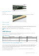
● Full-duplex data transfers and support for new transfer types ● Backward USB 2.0 compatibility ● New connectors and cable The topics below cover some of the most commonly asked questions regarding USB 3.0/USB 3.1 Gen 1. Speed Currently, there are 3 speed modes defined by the latest USB 3.0/USB 3.1 Gen 1 specification. They are Super-Speed, Hi-Speed and Full-Speed. The new SuperSpeed mode has a transfer rate of 4.8 Gbps.
● ● ● ● ● ● ● USB 3.0/USB 3.1 Gen USB 3.0/USB 3.1 Gen USB 3.0/USB 3.1 Gen Optical Media Drives Multimedia Devices Networking USB 3.0/USB 3.1 Gen 1 Flash Drives & Readers 1 Solid-state Drives 1 RAIDs 1 Adapter Cards & Hubs Compatibility The good news is that USB 3.0/USB 3.1 Gen 1 has been carefully planned from the start to peacefully co-exist with USB 2.0. First of all, while USB 3.0/USB 3.
● SuperSpeed USB (USB 3.1) data ● Supports HDMI 2.0a and is backwards compatible with previous versions HDMI 2.0 This topic explains the HDMI 2.0 and its features along with the advantages. HDMI (High-Definition Multimedia Interface) is an industry-supported, uncompressed, all-digital audio/video interface. HDMI provides an interface between any compatible digital audio/video source, such as a DVD player, or A/V receiver and a compatible digital audio and/or video monitor, such as a digital TV (DTV).
3 Major components of your system 13
Major components of your system 14 Major components of your system
1. 2. 3. 4. 5. 6. 7. 8. 9. 10. 11. 12. 13. 14. Cover System fan IO panel Power button module Optical drive Hard drive Bezel Hard drive Chasis Power supply unit System board Front fan Processor Heatsink assembly NOTE: Dell provides a list of components and their part numbers for the original system configuration purchased. These parts are available according to warranty coverages purchased by the customer. Contact your Dell sales representative for purchase options.
4 Disassembly and reassembly Topics: • • • • • • • • • • • • • • • • • • • • • • • • Chassis rubber feet Cover SD card—optional Bezel Hard drive PSU hinge Graphics card Memory module Speaker Coin cell battery Power supply unit Optical drive IO panel Solid state drive Power button module Heatsink assembly Blower and heat sink assembly Voltage regulator heat sink Front fan System fan Optional IO card Processor Intrusion switch System board Chassis rubber feet Removing the chassis rubber feet 1.
Figure 4.
Figure 5. Rear rubber feet removal Installing the chassis rubber feet 1. Insert one end of the rubber feet into the slot [1] and slide it to secure it to the system [2] and press the other end to secure it to the system [3].
Figure 6.
Figure 7. Rear rubber feet installation 2. Follow the procedure in After Working Inside Your Computer. Cover Removing the cover 1. Follow the procedure in Before Working Inside Your Computer. 2. Pull the release latch to release the cover [1]. NOTE: Release latch may have been secured with a security screw. Remove the security screw to release the cover.
3. Rotate the cover and lift the cover to remove it from the computer [2,3] Installing the cover 1. Align the hooks on the cover with the tabs on the chassis of the computer. 2. Rotate the cover until it clicks into place.
3. Follow the procedure in After Working Inside Your Computer. SD card—optional SD card is an optional component. Removing the SD card 1. Follow the procedure in Before Working Inside Your Computer. 2. Pull the SD card out of the system.
Installing the SD card 1. Insert the SD card into the SD card slot on the system.
2. Follow the procedure in After Working Inside Your Computer. Bezel Removing the front bezel 1. Follow the procedure in Before Working Inside Your Computer. 2. Remove the cover. 3. To remove the front bezel: a. Lift the retention tabs [1] to release the front bezel. b. Rotate and pull the front bezel to release the front bezel from the slots on the chassis [2,3].
Installing the front bezel 1. Hold the bezel and ensure that the hooks on the bezel align with notches on the computer. 2. Rotate the front bezel toward the computer. 3. Press the front bezel until the tabs click into place. 4. Install the cover. 5. Follow the procedure in After Working Inside Your Computer. Hard drive Removing the 3.5-inch hard drive 1. Follow the procedure in Before Working Inside Your Computer. 2. Remove the cover. 3.
5. Flex the hard drive bracket [1] and lift the hard drive from the hard drive bracket [2]. 6. To remove additional hard drive (if available), repeat steps from 3 to 5. Installing the 3.5-inch hard drive 1. Insert the holes on one side of the hard disk into the pins on the hard drive bracket and then place the hard drive into the bracket.
2. Slide the hard drive assembly into the hard drive bay [1]. 3. Connect the data cable and the power cable to the hard drive [2]. 4. To install additional hard drive, follow the steps from 1 to 3. 5. Install the cover. 6. Follow the procedure in After Working Inside Your Computer. Removing the 2.5-inch hard drive 1. Follow the procedure in Before Working Inside Your Computer. 2. Remove the cover. 3. Disconnect the data cables and the power cables from the respective connectors on the hard drives [1]. 4.
5. Disconnect the data cables and the power cables from the respective connectors on the hard drives [1]. 6. Press the blue securing bracket tabs and lift the hard drive bracket out of the bottom hard drive bays [2]. 7. Disconnect the SATA power cable from the connectors on the PSU [3].
8. Flex the hard drive bracket [1], lift the hard drive [2], and then slide out from the hard drive bracket [3]. NOTE: Follow the same procedure to remove another hard drive on the other side of the bracket. Installing the 2.5-inch hard drive 1. Insert the holes on one side of the hard disk into the pins on the hard drive bracket [1], and then place the hard drive into the bracket such that the pins on other side of the bracket is aligned with the holes on the hard drive [2].
4. Slide the hard drive assembly into the bottom hard drive bay [1]. 5. Connect the data cables and the power cables to the respective connectors on the hard drives [2]. 6. Route the power SATA cables along the guide to connect to the PSU [3].
7. Install the cover. 8. Follow the procedure in After Working Inside Your Computer. PSU hinge Opening the PSU hinge 1. Follow the procedure in Before working inside your computer. 2. Remove the cover: 3. Unlock the PSU release latches [1,2] 4. Rotate the PSU hinge as shown in the figure [3]. Closing the PSU hinge 1. Rotate the PSU hinge [1] 2. Unlock the PSU release latches to secure the PSU hinge to the system [2,3].
3. Install the cover: 4. Follow the procedure in After Working Inside Your Computer. Graphics card Removing the graphics card NOTE: You may see a PCIe card installed in some configurations. Follow the same steps except step 4 to remove the expansion card. 1. Follow the procedure in Before working inside your computer. 2. Remove the cover. 3. Disconnect the VGA power cable from the graphics cards in a dual graphics card configuration [1]. 4.
5. Open the PSU hinge. 6. Press the releasing clip and disconnect the graphics-card power cable from the connector on the graphics card [1]. 7. NOTE: A PCIe holder may not be required for system shipped with NVIDIA Quadro P4000 or RTX4000 dual graphics cards configuration. Lift the side of the PCIe holder that sits on the graphics card [2]. 8. Slide the PCIe holder to release the tab on the PCIE holder from the slot on the chassis [3]. 9.
Installing the graphics card NOTE: Follow the same steps except step 2 to install the expansion card. 1. Insert the graphics card to the connector on the system board.
Figure 8. Single graphics card Figure 9. Dual graphics card 2. Connect the graphics-card power cable to the connector on the graphics card for a single graphics card configuration [1]. 3. Insert the tab on the PCIe card holder into the slot on the chassis [2] and press until it is secured to the graphics card [3].
4. Close the PSU hinge. 5. Connect the VGA power cables to the dual graphics card configuration: a. Unroute the VGA power cables from the securing tabs on the PSU [1]. b. Lift the plastics latch to free the cables [2]. c. Connect the VGA power cables to the connectors on both the graphics card [3]. 6. Install the Cover. 7. Follow the procedure in After working inside your computer.
Memory module Removing the memory module 1. Follow the procedure in Before Working Inside Your Computer. 2. Remove the Cover. 3. Open the PSU hinge. 4. Press the memory module retention tabs on each side of the memory module [1]. 5. Lift the memory module out of the connectors on the system board [2]. Installing the memory module 1. Align the notch on the memory module with the tab on the memory module connector and insert the memory module into the memory module socket [1]. 2.
3. Close the PSU hinge. 4. Install the cover. 5. Follow the procedure in After Working Inside Your Computer. Speaker Removing speaker 1. Follow the procedure in Before working inside your computer. 2. Remove the: a. Cover b. PSU hinge 3. To remove speaker shipped with 60/ 85 W CPU system configuration: a. Disconnect the speaker cable from the connector on the system board [1]. b. Press the release tab [2] and pull the speaker out from front of the system chassis [3].
4. To remove speaker for system shipped with 95 W CPU system configuration : a. Disconnect the speaker cable from the system board [1]. b. Unroute the speaker cable from the tabs on the system board [2,3]. c. Press the release tab and pull the speaker out from front of the system chassis [4]. Installing the speaker 1.
a. Insert the speaker into the front slot on the system chassis and press it until it clicks into place [1]. b. Connect the speaker cable to the connector on the system board [2]. 2. To install speaker for system 95 W CPU system configuration : a. Replace the speaker into the rear portion of the chassis above the front fan [1]. b. Route the speaker cable along the tabs on the I/O port of the system board [2,3] and connect it to the system board [4]. 3. Close the PSU hinge. 4. Install the Cover. 5.
Coin cell battery Removing the coin cell battery 1. Follow the procedure in Before working inside your computer. 2. Remove the cover. 3. Open the PSU hinge. 4. To remove the coin cell battery: a. Press the release latch until the coin cell battery pops out [1]. b. Remove the coin cell battery from the connector on the system board [2]. Installing the coin cell battery 1. Hold the coin cell battery with the "+" sign facing up and slide it under the securing tabs at the positive side of the connector [1]. 2.
3. Close the PSU hinge. 4. Install the Cover. 5. Follow the procedure in After working inside your computer. Power supply unit Removing the power supply unit 1. Follow the procedure in Before Working Inside Your Computer. 2. Remove: a. Cover b. Heatsink assembly 3. Open the PSU hinge 4. Disconnect the following cables: ● For systems shipped with 65 W/80 W CPU system configurations: a. Disconnect the optical-drive power cable from the optical drive [1]. b.
● For systems shipped with heatsink assembly for 95 W CPU system configurations: a. b. c. d. Disconnect the optical-drive power cable from the optical drive [1]. Disconnect the CPU-power cable and system board power cable from the system board [2,3]. Disconnect the graphics-card power cable from the connector on the graphics card [4] Unroute the CPU-power cable from the routing guide on the chassis [5].
5. Close the PSU hinge. 6. To remove the power supply unit (PSU): a. Disconnect the hard-disk power cable [1]. NOTE: There could be up to four hard-disk power cables depending on the quantity of hard-disk drive installed. b. Remove the two #6-32x1/4'' screws that secure the power-supply bracket to the chassis [2] and lift the power-supply bracket from the system [3]. c. Remove the four #6-32x1/4'' screws that secure the power-supply unit to the chassis [4]. d. Lift the PSU off the chassis [5]. 7.
Installing the power supply unit 1. Connect the wiring harness to the 95 W CPU system configuration.
2. Insert the PSU into the PSU slot and slide it towards the back of the computer until it clicks into place [1]. 3. Replace the four #6-32x1/4'' screws to secure the PSU to the computer [2]. 4. Place the power supply bracket [3] and tighten the two #6-32x1/4'' screws to secure the PSU to the computer [4]. 5.
6. Open the PSU hinge. 7. Connect the following cables: ● For systems shipped with 65 W/80 W CPU system configuration: a. b. c. d. Route the CPU power cable through the routing guide on the chassis [1]. Connect the system board power cable [2]. Connect the CPU power cable to the connector on the system board [3]. Connect the optical-drive power cable to the connector on the optical drive [4]. ● : a. b. c. d. e. Route the CPU power cable through the routing guide on the chassis [1].
8. Install the: a. Heatsink assembly b. Cover 9. Close the PSU hinge. 10. Follow the procedure in After Working Inside Your Computer. Optical drive Removing the optical drive 1. Follow the procedure in Before Working Inside Your Computer. 2. Remove the cover. 3. Front bezel 4. Open the PSU hinge. 5. Disconnect the data cable and the power cable from the optical drive [1]. 6. Hold and pull the optical drive latch to unlock the optical drive [2].
7. Slide the optical drive from the front of the computer. 8. Remove the M2x2.5 screw that secures the optical-drive bracket to the optical drive [1] and remove the optical-drive bracket [2].
Installing the optical drive 1. Align the screw hole on the optical-drive bracket with the screw hole on the optical drive [1] and replace the M2x2.5 screw to secure the optical-drive bracket to the optical drive [2]. 2. Slide the optical drive into the drive bay from the front of the computer until it is secured. 3. Connect the data cable and power cable to the optical drive.
4. Close the PSU hinge. 5. Install the Front bezel 6. Install the cover. 7. Follow the procedure in After Working Inside Your Computer. IO panel Removing the IO panel 1. Follow the procedure in Before working inside your computer. 2. Remove the: a. Cover b. Front bezel c. Optical drive 3. Open the PSU hinge. 4. Disconnect the IO audio cable from the connector on the system board [1] and unroute the cable from routing guides next to the system board on the chassis [2].
5.
6. Remove the #6-32x1/4'' screw that secures the IO panel to the chassis.
7. Lift the IO panel to release the tabs on the IO panel from the slots on the chassis.
8. Pull the IO panel along with the cables to remove it from the IO panel slot on the chassis.
Installing the IO panel 1. Insert the cables through the IO panel slot on the chassis.
2. Insert the IO-panel tabs into the slots on the system [1] and tilt the IO panel to secure it to the system [2].
3. Replace the #6-32x1/4'' screw to secure the IO panel to the system.
4.
5. Route the IO audio cable through the routing clip next to the system board on the chassis [1]. 6. Connect the IO audio cable to the connector on the system board [2].
7. Install the: a. Optical drive b. Front bezel c. Cover 8. Close the PSU hinge. 9. Follow the procedure in After Working Inside Your Computer. Solid state drive Removing the PCIe SSD card NOTE: The instructions are applicable for removal of M.2 SATA SSD card also. 1. Follow the procedure in Before Working Inside Your Computer. 2. Remove the: a. cover. b. Graphics card. 3. Open the PSU hinge. 4. To remove the SSD card: a. Remove the M2x2.5 screw that secures the PCIe SSD card [1]. b.
Figure 10. 2242 SSD Installing the PCIe SSD card NOTE: The instructions are applicable for installation of M.2 SATA SSD card also. 1. Place the SSD thermal pad into the slot on the system board [1] .
2. Slide the PCIe SSD card into the slot and tighten the M2x2.5 screw to secure the SSD card to the system board [2,3]. Figure 11. 2242 SSD 3. Install the: a. Cover. b. Graphics card. 4. Close the PSU hinge. 5. Follow the procedure in After Working Inside Your Computer.
Power button module Removing power button module 1. Follow the procedure in Before working inside your computer. 2. Remove the: a. Cover b. Front bezel c. IO panel 3. Open the PSU hinge. 4. Disconnect the power button module cable from the connector on the system board [1]. 5. Remove the button module cable from the routing guides next to the system board on the chassis [2,3]. 6. Remove the adhesive tape that secures the power button module to the chassis [1]. 7.
Installing power button module 1. Insert the power button module into its slot on the system [1] and press the notches and secure it to the system [2]. 2. Affix the adhesive tape to secure the power button module to the system [3].
3. Route the power button module cable through the routing clips on the system [1,2]. 4. Connect the power button module cable to the connector on the system board [3].
5. Install the: a. b. c. d. IO panel Optical drive Front bezel Cover 6. Close the PSU hinge. 7. Follow the procedure in After Working Inside Your Computer. Heatsink assembly Removing heatsink assembly - 65 W or 80 W CPU These steps applies to system configurations shipped with 65 W or 80 W CPU. 1. Follow the procedure in Before working inside your computer. 2. Remove the Cover. 3. Open the PSU hinge. 4. To remove the heat sink assembly: a.
Installing heatsink assembly - 65 W or 80 W CPU These steps applies to system configurations shipped with 65 W or 80 W CPU. 1. Align the heat sink assembly with the screw holders on the system board and place it on the processor [1]. 2. Tighten the 4 captive screws to secure the heat sink assembly to the system board [2]. NOTE: Tighten the screws in a sequential order (1,2,3,4) as mentioned on the system board. 3. Connect the heat sink assembly cable to the connector on the system board [3].
4. Close the PSU hinge. 5. Install the cover. 6. Follow the procedure in After working inside your computer. Blower and heat sink assembly Removing heatsink assembly — 95 W CPU These steps applies to system configurations shipped with 95 W CPU. 1. Follow the procedure in Before working inside your computer. 2. Remove the cover. 3. Open the PSU hinge. 4. Remove the three #6-32x1/4'' screws that secure the blower to the heat-sink assembly [1]. 5. Flip over the blower and place it to a side [2].
6. Loosen the captive screws that secure the heat-sink assembly to the system board [1]. 7. Lift the heat-sink assembly off the system board [2]. 8. Disconnect the blower cable from the system board.
Installing the heatsink assembly — 95 W CPU These steps applies to system configurations shipped with 95 W CPU. 1. Route the blower cable through the heat sink assembly [1] and connect the blower cable to the connector on the system board [2]. 2. Place the heat-sink assembly over the processor. 3. Align the captive screws on the heat-sink assembly with the screw holes on the system board.
4. Tighten the captive screws that secure the heat-sink assembly to the system board. 5. Align the screw holes on the blower to the screw holes on the heat-sink assembly and place the blower over the heat-sink assembly [1]. 6. Replace the screws that secure the blower to the heat-sink assembly [2]. 7. Close the PSU hinge. 8. Install the cover. 9. Follow the procedure in After working inside your computer.
Voltage regulator heat sink Removing VR heatsink 1. Follow the procedure in Before working inside your computer. 2. Remove the: a. b. c. d. Cover Graphics card SSD Heatsink assembly 3. Open the PSU hinge. 4. Loosen the captive screws that secure the VR heatsink to the system board [1]. 5. Lift the VR heatsink from the system board [2]. Installing VR heatsink 1. Align the screws on the heatsink with the screw holders on the system board and place the VR heatsink on the system board [1]. 2.
3. Install the: a. b. c. d. Heatsink assembly SSD Graphics card Cover 4. Close the PSU hinge 5. Follow the procedure in After working inside your computer. Front fan Removing front fan 1. Follow the procedure in Before Working Inside Your Computer. 2. Remove the: a. Cover b. PSU hinge 3. Unroute the hard drive card cables from over the fan bracket.
4. Disconnect the front fan cable from the system board. 5. To release the front fan from the bracket, push the tab securing the front fan to the bracket.
6. Lift the front fan off the computer. 7. Release the fan cable from the hook on the fan frame [1] and flip over [2]. 8. Pry from all sides [3] and remove the fan from the frame [4].
Installing front fan 1. Replace the fan into the frame [1] and flip over [2]. 2. Route the fan cable through the hook on the fan frame [3]. 3. Replace the front fan on the fan bracket. 4. Press the tab to secure the front fan to the bracket on the computer.
5. Connect the front fan cable to the system board. 6. Route the hard drive card cables from over the front fan bracket.
System fan Removing system fan 1. Follow the procedure in Before Working Inside Your Computer. 2. Remove the: a. Cover b. PSU hinge c. Heatsink assembly 3. Disconnect the system fan cable from the connector on the system board. 4. Remove the #6-32x1/4'' screw that secures the system-fan bracket to the chassis [1]. 5. Slide the system-fan assembly towards the front of the computer to release it from the chassis and pull the system-fan assembly to remove it from the system [3].
6. Unroute the system fan cable from the routing channel on the system-fan bracket [1]. 7. To release the system fan from the bracket, pull the rubber grommets and remove the grommets securing the system fan to the bracket [2]. 8. Lift the system fan off the system-fan bracket [3]. Figure 12. Removing the chassis fan Installing system fan 1.
3. Align the grooves on the system-fan assembly with the holders on the chassis and slide the assembly [1]. 4. Replace the #6-32x1/4'' screw to secure the system-fan bracket to the chassis [2]. 5. Connect the system fan cable to the connector on the system board [3]. 6. Install the: a. Heatsink assembly b. PSU hinge c. Cover 7. Follow the procedure in After working inside your computer.
Optional IO card Removing optional IO card NOTE: You may see one of these cards-HDMI/DisplayPort/VGA/Type-C based on the additional component you may have ordered with the system. 1. Follow the procedure in Before working inside your computer. 2. Remove the cover. 3. Open the PSU hinge. 4. To remove the optional IO card: a. Disconnect the IO card cable from the connector on the system board [1]. b. Remove the two M3X3 screws that secure the IO card to the system [2]. c.
2. Insert the IO card into its slot from the inside of your computer [1] and replace the two M3X3 screws to secure the IO card to the system [2]. 3. Connect the IO card cable to the connector on the system board [3]. 4. Close the PSU hinge. 5. Install the cover.
Processor Removing the processor 1. Follow the procedure in Before Working Inside Your Computer. 2. Remove the: a. Cover b. PSU hinge c. Heatsink assembly 3. To remove the processor: a. Release the socket lever by pushing the lever down and out from under the tab on the processor shield [1]. b. Lift the lever upward and lift the processor shield [2]. c. Lift the processor out of the socket [3]. Installing the processor 1.
4. Install the: a. Heatsink assembly b. PSU hinge c. Cover 5. Follow the procedure in After Working Inside Your Computer. Intrusion switch Removing intrusion switch 1. Follow the procedure in Before working inside your computer. 2. Remove the cover. 3. Open the PSU hinge. 4. To remove the intrusion switch: a. Disconnect the intrusion switch cable from the connector on the system board [1]. b. Unroute the intrusion switch cable from the routing clips on the chassis [2]. c.
Installing intrusion switch 1. Slide the intrusion switch into the slot on the computer [1]. 2. Route the intrusion switch cable through the routing clips on the chassis [2]. 3. Connect the intrusion switch cable to the connector on the system board [3]. 4. Close the PSU hinge. 5. Install the cover.
6. Follow the procedure in After working inside your computer. System board Removing the system board 1. Follow the procedure in Before Working Inside Your Computer. 2. Remove the: a. b. c. d. e. f. g. h. i. Cover PSU hinge Memory module Graphics card SSD Heatsink assembly VR heat sink (for models shipped with 95 W heatsink assembly) Optional IO card Processor 3.
5. Remove the following cables: ● Speaker cable [1] ● IO audio cable [2] 6. Remove the 8 #6-32x1/4'' screws that secure the system board to the chassis.
7. Lift the system board at an angle and remove it from the computer. Installing the system board 1. Slide the I/O ports on the system board into the slots on the chassis and place the system board on the chassis [1]. Align the screw holes on the system board with the screw holes on the chassis [2].
2. Replace the 8 #6-32x1/4'' screws that secure the system board to the chassis. 3.
4. Route and connect the following cables: ● ● ● ● ● ODD SATA cable [1] Primary HDD SATA cable [4] IO USB cable [3] Type-C cable [4] SD card cable [5] 5.
● CPU power cable [2] ● System fan cable, intrusion cable, and IO panel cable [3] 6. Install the: a. b. c. d. e. f. g. h. i. Optional IO card Processor VR heat sink (for models shipped with 95W heat sink assembly) Heatsink assembly (for models shipped with 95W heat sink assembly) SSD Graphics card Memory module PSU hinge Cover 7. Follow the procedure in After Working Inside Your Computer.
5 Troubleshooting Topics: • • • • • Power supply unit Built-in Self Test Enhanced Pre-Boot System Assessment — ePSA diagnostics Diagnostics Diagnostic error messages System error messages Power supply unit Built-in Self Test Precision 3630 supports a new power supply unit Built-in Self Test (BIST). You can test the health of the power system by pressing the test button or by connecting the power cord. When the power cord is connected, the self-test LED is lit for 3-5 seconds indicating PSU functionality.
CAUTION: Ensure that you take adequate safety precautions before accessing the components on your computer. See the removing and replacing instructions in the service manual for procedure to access the power-supply unit and its cables. 2. Disconnect the power supply unit cables from the system board and other components. 3. Press the PSU BIST button. ● If the LED turns on and remains on while the BIST button is pressed, it indicates that the power-supply unit is functional.
NOTE: To determine the device that is failing, see the light patterns . Off – System is in hibernation or turned off. The power status light blinks amber along with beep codes indicating failures. For example, the power status light blinks amber two times followed by a pause, and then blinks white three times followed by a pause. This 2,3 pattern continues until the computer is turned off indicating the Recovery image is not found.
Table 3. Diagnostic error messages (continued) Error messages Description DRIVE NOT READY The operation requires a hard drive in the bay before it can continue. Install a hard drive in the hard drive bay. ERROR READING PCMCIA CARD The computer cannot identify the ExpressCard. Reinsert the card or try another card. EXTENDED MEMORY SIZE HAS CHANGED The amount of memory recorded in non-volatile memory (NVRAM) does not match the memory module installed in the computer. Restart the computer.
Table 3. Diagnostic error messages (continued) Error messages Description during the boot routine. Run the Keyboard Controller test in Dell Diagnostics. KEYBOARD DATA LINE FAILURE For external keyboards, check the cable connection. Run the Keyboard Controller test in Dell Diagnostics. KEYBOARD STUCK KEY FAILURE For external keyboards or keypads, check the cable connection. Restart the computer, and avoid touching the keyboard or keys during the boot routine. Run the Stuck Key test in Dell Diagnostics.
Table 3. Diagnostic error messages (continued) Error messages Description problem persists, try to restore the data by entering the System Setup program, then immediately exit the program. If the message reappears, Contact Dell. TIME-OF-DAY CLOCK STOPPED The reserve battery that supports the system configuration settings may require recharging. Connect your computer to an electrical outlet to charge the battery. If the problem persists, Contact Dell.
Table 4.
6 Getting help Topics: • Contacting Dell Contacting Dell NOTE: If you do not have an active Internet connection, you can find contact information on your purchase invoice, packing slip, bill, or Dell product catalog. Dell provides several online and telephone-based support and service options. Availability varies by country and product, and some services may not be available in your area. To contact Dell for sales, technical support, or customer service issues: 1. Go to Dell.com/support. 2.
A Cable cover The cable cover for Precision Tower 3630 helps protect ports and cables connected to the system. Follow these steps to install the cable cover on the system chassis. NOTE: Images shown below are for representation only and may vary depending on the system's configuration. 1. Insert the tab on the security-lock metal bracket into the slot on the rear side of the system [1] and rotate to align the holes on the metal bracket with screw holders on the chassis [2] 2.
4. Lift the tab [1] to release and pull the cable tie from the slot on the cable release latch [2]. 5. Align the cable release latch on the system chassis slot [1]. Tighten the screw to secure the cable release latch to the system chassis [2].
6. Route the cables through the slot of the cable cover [1], and connect them to their respective ports on the system [2]. Secure the cable with the cable tie and lock the tab in place [3]. CAUTION: Take care not to break or bend the delicate plastic hooks. 7. Align the plastic hooks of the cable cover to the slots on the system .
8. Gently press down on the cable cover until it clicks into place [1]. Slide the latch towards the chassis [2] to lock the cable cover in place. NOTE: For added security, use the Padlock ring to secure the system. 9. To remove the cable cover: a. Slide the latch away from the chassis to unlock the cable cover [1]. b. Lift the cable cover away from the system chassis [2].
10. Pull the cable cover to release it from the chassis. 11. Open the tab and unroute the cables from cable tie [1], disconnect the cables from the ports on the system [2]. Remove the cables from the slot of the cable cover [3].
Cable cover
B Dust filter The dust filter for the Precision Tower 3630 helps protect the system from fine dust particles. After installation of the dust filter, the BIOS can be enabled to generate a preboot reminder to clean or replace the dust filter based on the time interval set. Follow these steps to install the dust filter: 1. Align the plastic tabs of the dust filter to the slots on the system chassis and gently press to ensure that the dust filter fits firmly onto the system. 2. To remove the dust filter: a.
3. Restart the system and press F2 to enter the BIOS Setup menu. 4. In the BIOS Setup menu, navigate to System Configuration > Dust Filter Maintenance and select from any of the following intervals: 15, 30, 60, 90, 120, 150, or 180 days. NOTE: Default setting: Disabled. NOTE: Alerts are generated only during a system reboot and not during normal OS operation. To clean the dust filter, brush or gently vacuum and then wipe down the external surfaces with a moist cloth.