Precision 3650 Tower Service Manual Regulatory Model: D24M Regulatory Type: D24M005 April 2021 Rev.
註、警示與警告 註: 「註」表示可以幫助您更有效地使用產品的重要資訊。 警示: 「警示」表示有可能會損壞硬體或導致資料遺失,並告訴您如何避免發生此類問題。 警告: 「警告」表示可能的財產損失、人身傷害或死亡。 © 2021 Dell Inc. 或其子公司。版權所有,翻印必究。Dell、EMC 與其他商標均為 Dell Inc.
1 拆裝電腦內部元件 安全指示 請遵守以下安全規範,以避免電腦受到潛在的損壞,並確保您的人身安全。除非另有說明,否則本文件中包含的每個程序均假設 您已閱讀電腦隨附的安全資訊。 警告: 拆裝電腦內部元件之前,請先閱讀電腦隨附的安全資訊。如需更多有關安全性的資訊最佳實務,請參閱 Regulatory Compliance (法規遵循) 首頁 www.dell.com/regulatory_compliance。 警告: 打開電腦機箱蓋或面板之前,請先斷開所有電源。拆裝電腦內部元件之後,請先裝回所有護蓋、面板和螺絲,然後再 連接電源插座。 警示: 為避免損壞電腦,請確保工作表面平整、乾燥、乾淨。 警示: 為避免損壞元件和插卡,請握住元件和插卡的邊緣,並避免碰觸插腳和接點。 警示: 您只能在 Dell 技術援助團隊的授權或指導之下執行故障排除和維修。由未經 Dell 授權的維修造成的損壞不在保固範 圍之內。請參閱產品隨附或 www.dell.
安全預防措施 安全預防措施章節詳細說明執行任何拆卸指示前採取的主要步驟。 在您執行任何包括拆卸或重組的故障/ 修復程序前,請遵守以下安全預防措施 : ● 關閉系統及所有連接的周邊裝置。 ● 拔除系統和所有連接之周邊裝置的 AC 電源。 ● 拔除系統的所有網路纜線、電話和電信線路。 ● 進行任何平板電腦筆記型電腦桌上型電腦內部作業時,請使用 ESD 現場維修套件,以避免靜電放電 (ESD) 損壞。 ● 卸下任何系統元件後,請小心地將卸下的元件放在防靜電墊上。 ● 穿著具備非導電橡膠鞋底的鞋子,以降低發生觸電的可能性。 備用電源 含備用電源的 Dell 產品必須先斷開電源,才能打開外殼。整合備用電源的系統在關機時基本上還是有電。內部電源可讓您遠端 開啟系統 (透過 LAN 喚醒) 以及讓系統暫時進入睡眠模式,而且有其他進階電源管理功能。 斷開電源,並按住電源按鈕 15 秒,這麼做應該可釋放主機板的殘餘電力。從平板電腦筆記型電腦中取出電池。 搭接 搭接是一種將兩個或多個接地導體連接到相同電位的方式。這必須透過現場維修靜電放電 (ESD) 套件來完成。連接搭接線時, 請確定它連接的是裸金屬;切勿連接到已上色或非金
● 防靜電墊 – 防靜電墊會消除靜電,而且可讓您在維修程序期間將零件置於其上。使用防靜電墊時,您的腕帶必須緊貼手臂, 而且搭接線必須連接至防靜電墊以及正在處理之系統上的任何裸金屬。部署妥當後,就可以從 ESD 袋取出維修零件,並直接 放置放在墊子上。您可以安心地將 ESD 敏感物品放在手中、ESD 墊上、系統中或袋子裡面。 ● 腕帶和搭接線 – 如果不需要使用 ESD 墊,或是已經將 ESD 墊連接至防靜電墊以保護暫時放置在墊子上的硬體時,腕帶和搭 接線就可直接連接您的手腕和硬體上的裸金屬。腕帶與您皮膚、ESD 墊及硬體之間搭接線的實體連結,都稱為搭接。現場維 修套件只能搭配腕帶、防靜電墊及搭接線使用。切勿使用無線腕帶。請隨時注意,腕帶的內部電線會因為正常磨損而易於損 壞,而且必須以腕帶測試工具定期檢查,以避免 ESD 硬體意外損壞。建議每週至少測試腕帶和搭接線一次 ● ESD 腕帶測試工具 – ESD 腕帶內部的電線容易因使用久了而損壞。使用未受監控的套件時,最佳作法是在每次維修通話之 前定期測試腕帶,並且每週至少測試一次。腕帶測試工具便是執行此測試的最佳方法。如果您沒有自己的腕帶測試工具,請 洽詢當地辦公
2 拆卸與重組 建議的工具 本文件中的程序可能需要以下工具: ● 0 號十字螺絲起子 ● 1 號十字螺絲起子 ● 2 號十字螺絲起子 ● 塑膠拆殼棒 - 建議現場技術人員使用 ● T-30 Torx 螺絲起子 螺絲清單 下表顯示不同元件的螺絲清單和圖片。 註: 卸下元件的螺絲時,建議您記下螺絲類型、螺絲數量,然後將這些螺絲置於螺絲收納盒中。這是為了在裝回元件時,能 確實還原正確的螺絲數量和螺絲類型。 註: 部分電腦具有磁性表面。裝回元件時,請確定螺絲並未附著在這類表面上。 註: 視您訂購的組態而定,螺絲顏色可能會有所不同。 表 1. 螺絲清單 元件 螺絲類型 數量 側蓋 M6-32x12.7 1 M.2 2280 固態硬碟 M2x3.5 1 WLAN 卡 M2x3.
系統的主要元件 1. 2. 3. 4. 5. 6. 7. 8. 9. 10. 11. 12. 13. 14. 15. 側蓋 記憶體模組 I/O 面板 風扇和散熱器組件 處理器 固態硬碟 電源按鈕 主機板 機箱 前蓋 3.5 吋硬碟 系統風扇 顯示卡 光碟機 (選配) 電源供應器 側蓋 卸下側蓋 事前準備作業 1.
拆卸與重組
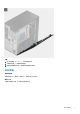
步驟 1. 卸下單顆螺絲 (M6.32x12.7),以解鎖釋放閂鎖。 2. 拉動釋放閂鎖,以從電腦鬆開側蓋。 3.
步驟 1.
2. 將側蓋上的彈片對準機箱上的插槽。 3. 輕輕按壓側蓋。 4. 釋放閂鎖會自動將側蓋鎖定至電腦。 5. 裝回螺絲 (M6.32x12.7) 以固定釋放閂鎖。 後續步驟 1. 按照拆裝電腦內部元件之後中的程序操作。 電源供應器固定框架 打開電源供應器固定框架 事前準備作業 1. 按照拆裝電腦內部元件之前中的程序操作。 2.
步驟 1. 將電腦右側面朝下放好。 2. 推動 PSU 鉸接和 PSU 釋放閂鎖,以解鎖 PSU 固定框架。 3.
拆卸與重組 13
步驟 1. 旋轉 PSU 固定框架。 2. 壓下 PSU 固定框架,然後推動 PSU 鉸接和 PSU 釋放閂鎖,以鎖定 PSU 固定框架。 後續步驟 1. 安裝側蓋。 2. 按照拆裝電腦內部元件之後中的程序操作。 前蓋 卸下前框 事前準備作業 1. 按照拆裝電腦內部元件之前中的程序操作。 2.
步驟 1. 撬起固定彈片,從電腦鬆開前框。 2. 稍微拉動前框並輕輕旋轉,從電腦機箱的插槽鬆開前蓋上的其他彈片。 3.
步驟 1. 調整前框的位置,將前框上的彈片固定架對準機箱上的插槽。 2. 按下前蓋直到所有彈片卡至定位。 後續步驟 1. 安裝側蓋。 2. 按照拆裝電腦內部元件之後中的程序操作。 記憶體模組 卸下記憶體模組 事前準備作業 1. 按照拆裝電腦內部元件之前中的程序操作。 2. 卸下側蓋。 3.
步驟 1. 從記憶體模組兩側拉出固定夾,直至記憶體模組彈起。 2.
步驟 1. 將記憶體模組上的槽口對準記憶體模組插槽上的彈片。 2. 將記憶體模組傾斜推入插槽,並向下按壓記憶體模組,直至其卡入到位。 註: 如果未聽到卡嗒聲,請卸下記憶體模組並重新安裝它。 後續步驟 1. 闔上 PSU 固定框架。 2. 安裝側蓋。 3. 按照拆裝電腦內部元件之後中的程序操作。 固態硬碟 卸下 M.2 2280 PCIe 固態硬碟 事前準備作業 1. 按照拆裝電腦內部元件之前中的程序操作。 2. 卸下側蓋。 3.
步驟 1. 卸下將固態硬碟固定在系統主機板上的螺絲 (M2x3.5)。 2. 從主機板推動並卸下固態硬碟。 安裝 M.
步驟 1. 將固態硬碟上的凹槽對準固態硬碟連接器上的彈片。 2. 以 45 度角將固態硬碟插入系統主機板上的插槽。 3. 裝回將 M.2 2280 固態硬碟固定至系統主機板的螺絲 (M2x3.5)。 後續步驟 1. 闔上 PSU 固定框架。 2. 安裝側蓋。 3. 按照拆裝電腦內部元件之後中的程序操作。 2.5 吋硬碟機 卸下 2.5 吋硬碟 事前準備作業 1. 按照拆裝電腦內部元件之前中的程序操作。 2. 卸下側蓋。 3. 打開 PSU 固定框架。 關於此工作 下圖顯示 2.
步驟 1. 從 2.5 吋硬碟模組上的連接器拔下硬碟資料纜線和電源線。 2. 壓下硬碟托架兩側的釋放彈片,將其從電腦機箱上的插槽鬆開。 3. 將硬碟組件從電腦提起取出。 註: 記下硬碟的方向,以便正確裝回。 安裝 2.5 吋硬碟 事前準備作業 如果要更換元件,請先卸下現有元件,再開始執行安裝程序。 關於此工作 下圖顯示 2.
步驟 1. 壓下硬碟托架上的釋放彈片,然後稍微向後對齊,以將硬碟組件插入電腦機箱上的插槽。 2. 將硬碟資料纜線和電源線連接至 2.5 吋硬碟模組上的連接器。 後續步驟 1. 闔上 PSU 固定框架。 2. 安裝側蓋。 3. 按照拆裝電腦內部元件之後中的程序操作。 3.5 吋硬碟機 卸下 3.5 吋硬碟組件 事前準備作業 1. 按照拆裝電腦內部元件之前中的程序操作。 2. 卸下側蓋。 3. 打開 PSU 固定框架。 關於此工作 下圖顯示 3.
步驟 1. 扳起固定於顯示卡上的 PCIe 固定座側邊。 2. 推動 PCIe 固定座,以從機箱上的插槽鬆開彈片。 3. 從 3.5 吋硬碟模組上的連接器拔下硬碟資料纜線和電源線。 4. 壓下硬碟托架兩側的釋放彈片,將其從電腦機箱上的插槽鬆開。 5. 將硬碟組件從電腦提起取出。 註: 記下硬碟的方向,以便正確裝回。 安裝 3.5 吋硬碟組件 事前準備作業 如果要更換元件,請先卸下現有元件,再開始執行安裝程序。 關於此工作 下圖顯示 3.
步驟 1. 壓下硬碟托架上的釋放彈片並將其對齊,以將硬碟組件插入電腦機箱上的插槽。 2. 將硬碟資料纜線和電源線連接至 3.5 吋硬碟模組上的連接器。 3. 將 PCIe 卡座上的彈片插入機箱上的插槽,然後輕輕壓下直到其固定至顯示卡。 後續步驟 1. 闔上 PSU 固定框架。 2. 安裝側蓋。 3. 按照拆裝電腦內部元件之後中的程序操作。 WLAN 卡 卸下 WLAN 卡 事前準備作業 1. 按照拆裝電腦內部元件之前中的程序操作。 2. 卸下側蓋。 3.
關於此工作 下圖顯示無線網卡的位置,並以圖示解釋卸除程序。 步驟 1. 卸下將 WLAN 卡固定至系統主機板上的 (M2x3.5) 螺絲。 2. 從 WLAN 卡提起取出 WLAN 卡托架。 3. 從 WLAN 卡上拔下天線纜線。 4.
步驟 1. 將天線纜線連接至 WLAN 卡。 下表提供電腦 WLAN 卡的天線纜線顏色配置。 表 2. 天線纜線顏色配置 無線網卡上的連接器 天線纜線的顏色 主要 (白色三角形) 白色 輔助 (黑色三角形) 黑色 2. 放置 WLAN 卡托架以固定 WLAN 天線纜線。 3. 將 WLAN 卡插入主機板上的連接器。 4. 裝回將塑膠彈片固定至 WLAN 卡的 (M2x3.5) 螺絲。 後續步驟 1. 闔上 PSU 固定框架。 2. 安裝側蓋。 3.
薄型光碟機 卸下薄型光碟機 事前準備作業 1. 按照拆裝電腦內部元件之前中的程序操作。 2. 卸下側蓋。 3. 打開 PSU 固定框架。 關於此工作 下圖顯示薄型 ODD 的位置,並以圖示解釋卸除程序。 步驟 1. 從薄型 ODD 拔下資料纜線和電源纜線。 2. 拉動固定彈片,以從機箱鬆開薄型 ODD。 3.
安裝薄型光碟機 事前準備作業 如果要更換元件,請先卸下現有元件,再開始執行安裝程序。 關於此工作 下圖顯示薄型 ODD 的位置,並以圖示解釋安裝程序。 步驟 1. 將薄型 ODD 組件插入 ODD 插槽。 2. 將薄型 ODD 組件滑入,直到卡入定位。 3. 將電源纜線和資料纜線穿過固定導軌,然後將纜線連接至薄型 ODD。 後續步驟 1. 闔上 PSU 固定框架。 2. 安裝側蓋。 3. 按照拆裝電腦內部元件之後中的程序操作。 圖形卡 卸下顯示卡 事前準備作業 1. 按照拆裝電腦內部元件之前中的程序操作。 2. 卸下側蓋。 3.
關於此工作 下圖顯示顯示卡的位置,並以圖示解釋卸除程序。 步驟 1. 找到顯示卡 (PCI-Express)。 2. 扳起固定於顯示卡上的 PCIe 固定座側邊。 3. 推動 PCIe 固定座,以將其從機箱上的插槽鬆開。 4.
步驟 1. 將顯示卡對準主機板上的 PCI Express 卡連接器。 2. 使用對齊導柱,將顯示卡連接至連接器,然後向下壓緊。請確定插卡已裝妥。 3. 將 PCIe 卡座上的彈片插入機箱上的插槽,然後輕輕壓下直到其固定至顯示卡。 後續步驟 1. 闔上 PSU 固定框架。 2. 安裝側蓋。 3. 按照拆裝電腦內部元件之後中的程序操作。 系統風扇 卸下系統風扇 事前準備作業 1. 按照拆裝電腦內部元件之前中的程序操作。 2. 卸下側蓋。 3.
步驟 1. 從主機板上的連接器拔下系統風扇纜線。 2. 卸下將系統風扇托架固定至電腦機箱的單顆 (#6-32) 螺絲。 3.
步驟 1. 調整系統風扇位置,將其對準電腦機箱上的插槽。 2. 裝回將系統風扇固定至電腦機箱的單顆 (#6-32) 螺絲。 後續步驟 1. 闔上 PSU 固定框架。 2. 安裝側蓋。 3. 按照拆裝電腦內部元件之後中的程序操作。 幣式電池 卸下幣式電池 事前準備作業 1. 2. 3. 4.
步驟 1. 使用塑膠拆殼棒,從系統主機板上的插槽中輕輕撬起幣式電池。 2. 從電腦取下幣式電池。 安裝幣式電池 事前準備作業 如果要更換元件,請先卸下現有元件,再開始執行安裝程序。 關於此工作 下圖顯示幣式電池的位置,並以圖示解釋安裝程序。 步驟 1. 插入幣式電池且「+」符號面向上,然後將其推入連接器正極一側的固定彈片下面。 2.
後續步驟 1. 安裝接電的 GPU。 註: 只要系統配置接電的 GPU,就必須進行此步驟。 2. 闔上 PSU 固定框架。 3. 安裝側蓋。 4. 按照拆裝電腦內部元件之後中的程序操作。 處理器風扇和散熱器組件 卸下處理器風扇和散熱器組件 事前準備作業 1. 按照拆裝電腦內部元件之前中的程序操作。 警告: 散熱器在正常作業時可能會很熱。讓散熱器有足夠的時間冷卻再觸碰它。 警示: 為確保處理器獲得最佳冷卻效果,請勿碰觸散熱器上的導熱區域。皮膚上的油脂會降低熱脂的導熱能力。 2. 卸下側蓋。 3. 打開 PSU 固定框架。 關於此工作 下圖顯示處理器風扇和散熱片的位置,並以圖示解釋卸除程序。 步驟 1. 從系統主機板上的連接器拔下處理器風扇纜線。 2. 鬆開將處理器風扇和散熱器組件固定至主機板的四顆緊固螺絲。 3.
安裝處理器風扇和散熱器組件 事前準備作業 註: 如果要更換處理器或散熱器,請使用套件隨附的散熱膏以確保導熱性。 關於此工作 下圖顯示處理器風扇和散熱片組件的位置,並以圖示解釋安裝程序。 步驟 1. 將處理器風扇和散熱器組件上的螺絲孔與主機板上的螺絲孔對齊。 2. 鎖緊將處理器風扇和散熱器組件固定至主機板的四顆緊固螺絲。 3. 將處理器風扇纜線連接至系統主機板上的連接器。 後續步驟 1. 闔上 PSU 固定框架。 2. 安裝側蓋。 3. 按照拆裝電腦內部元件之後中的程序操作。 處理器 卸下處理器 事前準備作業 1. 2. 3. 4.
註: 處理器在電腦關閉後仍可能很燙。請等到處理器冷卻後再卸下。 關於此工作 下圖顯示處理器的位置,並以圖示解釋卸除程序。 步驟 1. 向下按壓釋放拉桿並將其推離處理器,使其從固定彈片鬆開。 2. 扳起拉桿,並抬起取出處理器護蓋。 警示: 卸下處理器時,請勿碰觸插槽內的任何插腳,或讓任何物品掉落在插槽內的插腳上。 3.
步驟 1. 確保處理器插槽上的釋放拉桿已完全展開到打開位置。 2. 將處理器上的槽口與處理器插槽上的槽口對齊,然後將處理器放入處理器插槽中。 註: 處理器的插腳 1 角落有一個三角形,可用來對準處理器插槽之插腳 1 角落上的三角形。正確安插處理器後,全部四個 角會等高對齊。如果處理器的一個或多個角高於其他角,表示處理器未安插好。 3. 處理器完全插入插槽之後,請向下轉動釋放拉桿,並將其置於處理器護蓋彈片下方。 後續步驟 1. 2. 3. 4. 安裝處理器風扇和散熱器組件。 闔上 PSU 固定框架。 安裝側蓋。 按照拆裝電腦內部元件之後中的程序操作。 電源按鈕 卸下電源按鈕 事前準備作業 1.
2. 卸下側蓋。 3. 打開 PSU 固定框架。 4. 卸下前蓋。 關於此工作 下圖顯示電源按鈕的位置,並以圖示解釋卸除程序。 步驟 1. 從主機板上的連接器拔下電源按鈕纜線。 2. 按下電源按鈕頭上的釋放彈片,然後將電源按鈕纜線從電腦機箱正面滑出。 3. 將電源按鈕纜線從電腦拉出。 安裝電源按鈕 事前準備作業 如果要更換元件,請先卸下現有元件,再開始執行安裝程序。 關於此工作 下圖顯示電源按鈕開關的位置,並以圖示解釋安裝程序。 步驟 1. 將電源按鈕纜線從電腦正面插入插槽,然後按下電源按鈕頭,直至卡入機箱。 2. 將電源按鈕纜線對準連接至系統主機板上的連接器。 後續步驟 1. 2. 3. 4. 安裝前蓋。 闔上 PSU 固定框架。 安裝側蓋。 按照拆裝電腦內部元件之後中的程序操作。 入侵偵測開關 卸下入侵偵測開關 事前準備作業 1. 按照拆裝電腦內部元件之前中的程序操作。 2. 卸下側蓋。 3.
步驟 1. 從系統主機板的連接器拔下入侵偵測開關纜線。 2.
步驟 1. 將入侵偵測開關插入其對應的插槽,然後推動開關以將其固定至插槽。 2. 將入侵偵測開關纜線連接至系統主機板上的連接器。 後續步驟 1. 闔上 PSU 固定框架。 2. 安裝側蓋。 3. 按照拆裝電腦內部元件之後中的程序操作。 I/O 前面板 卸下 I/O 面板 事前準備作業 1. 2. 3. 4.
步驟 1. 從主機板上的連接器拔下 I/O 音訊、SD 卡、USB Type-C 及 I/O USB 纜線。 2.
步驟 1. 將 I/O 面板插入插槽,然後推動以將其固定至插槽。 2. 裝回將 I/O 面板固定至電腦機箱的單顆 (#6-32) 螺絲。 3. 將 I/O 音訊、SD 卡、USB Type-C 及 I/O USB 纜線連接至主機板上的連接器。 後續步驟 1. 2. 3. 4.
主機板 主機板配置 1. E24 連接器 2. 選配的 2.5 GbE RJ-45 連接器 3. 處理器電源連接器 4. E25 連接器 5. 系統風扇連接器 6. 機箱入侵偵測連接器 7. 記憶體模組插槽 8. 電源按鈕連接器 9. 主機板電源連接器 10. SD 卡連接器 11. 前面板 USB 連接器 12. 前面板 USB-C 連接器 13. 前面板 USB 電源連接器 14. 幣式電池 15. SATA 0 (藍色)、SATA 1 (白色)、SATA 2 及 SATA 3 (黑色) 連接器 16. M.2 PCIe SSD 連接器 17. 系統風扇連接器 (正面) 18. Thunderbolt 4 AIC 連接器 19. E20 連接器 20. E23 連接器 21. CAC_PIV 電源連接器 22. P30 連接器 23. CMOS 時鐘重設跳線 24. 25.
26. 27. 硬碟風扇連接器 28. 前面板音訊連接器 29. 內建喇叭連接器 30. M.2 PCIe SSD 連接器 31. 全高 PCIe x4 插槽 (開放式) 32. PCI-32 插槽 33. 全高 PCIe x16 插槽 34. M.2 PCIe SSD 連接器 35. 處理器風扇連接器 36. 處理器插槽 37. 選配的顯示卡連接器 38. USB C 連接器 卸下主機板 事前準備作業 1. 按照拆裝電腦內部元件之前中的程序操作。 註: 您電腦的服務標籤位在主機板上。在更換主機板後,您必須在 BIOS 設定程式中輸入服務標籤。 註: 更換主機板會移除您使用 BIOS 設定程式對 BIOS 所做的變更。在更換主機板後您必須再次進行適當的變更。 註: 將纜線從主機板拔下之前,請先記下連接器的位置,以便在更換主機板後,可以將它們連接回正確位置。 2. 3. 4. 5. 6. 7. 8. 9. 10. 11. 卸下側蓋。 卸下前蓋。 打開 PSU 固定框架。 卸下記憶體模組。 卸下 WLAN。 卸下 M.
拆卸與重組 45
步驟 1. 將連接主機板的所有纜線拔下。 2. 卸下將主機板固定至機箱的八顆 (#6-32) 螺絲。 3.
步驟 1. 將主機板上的後 I/O 連接埠推入機箱上的後 I/O 插槽。 2. 將主機板上的螺絲孔與機箱上的螺絲孔對齊。 3. 裝回將主機板固定至機箱的八顆螺絲 (#6-32)。 4. 穿入所有纜線,並將所有纜線連接至系統主機板上的連接器。 後續步驟 1. 2. 3. 4. 5. 6. 7. 8. 9. 10. 11. 安裝處理器。 安裝處理器風扇和散熱器組件。 安裝幣式電池。 安裝顯示卡。 安裝 M.
3 驅動程式與下載 驅動程式與下載 進行故障排除、下載或安裝驅動程式時,建議您閱讀 Dell 知識庫文章以及驅動程式和下載常見問題 SLN128938。 48 驅動程式與下載
4 系統設定 Boot Sequence (開機順序) Boot Sequence (開機順序) 可讓您略過系統設定定義的開機裝置順序,並直接開機至特定裝置 (例如:光碟機或硬碟)。在開機 自我測試 (POST) 期間,當螢幕上出現 Dell 標誌時,您可以: ● 按下 F2 鍵存取系統設定 ● 按下 F12 鍵顯示單次開機功能表 單次開機功能表會顯示可用的開機裝置,包括診斷選項。可用的開機功能表選項有: ● 抽取式磁碟機 (若有) ● STXXXX 磁碟機 (若有) 註: XXX 代表 SATA 磁碟機編號。 ● 光碟機 (若有) ● SATA 硬碟 (如果有的話) ● 診斷 開機順序畫面也會顯示選項,讓您存取系統設定畫面。 系統設定選項 註: 視電腦和安裝的裝置而定,本節列出的項目不一定會顯示。 表 3.
表 3.
表 4. 系統設定選項 – 開機組態選單 (續) 開機組態 安全開機 Enable Secure Boot 啟用或停用安全開機功能。 此選項預設為未啟用。 Secure Boot Mode 啟用或停用以變更安全開機模式選項。 部署模式預設為已啟用。 Expert Key Management Enable Custom Mode 啟用或停用自訂模式。 自訂模式選項預設為未啟用。 Custom Mode Key Management 選擇專家金鑰管理自訂值。 表 5.
表 6. 系統設定選項 – 儲存裝置選單 (續) 存放時 Enable Smart Reporting (啟用 SMART 報 告) 啟用或停用在電腦啟動時使用自我監測分析報告技術 (SMART)。 啟用 SMART 報告 選項預設為未啟用。 Drive Information (磁碟機資訊) SATA-0 類型 顯示電腦的 SATA HDD 類型資訊。 裝置 顯示電腦的 SATA HDD 裝置資訊。 SATA-1 類型 顯示電腦的 SATA HDD 類型資訊。 裝置 顯示電腦的 SATA HDD 裝置資訊。 SATA-2 類型 顯示電腦的 SATA HDD 類型資訊。 裝置 顯示電腦的 SATA HDD 裝置資訊。 SATA-3 類型 顯示電腦的 SATA HDD 類型資訊。 裝置 顯示電腦的 SATA HDD 裝置資訊。 M.2 PCIe SSD-0 類型 顯示電腦 M.2 PCIe SSD-0 類型資訊。 裝置 顯示電腦 M.2 PCIe SSD-0 裝置資訊。 M.2 PCIe SSD-1 類型 顯示電腦 M.
表 8. 系統設定選項 – 連線選單 連線 網路控制器組態 內建 NIC 控制內建 LAN 控制器。 透過 PXE 啟用選項預設為啟用。 Wireless Device Enable WLAN 啟用或停用內建 WLAN 裝置 此選項預設為啟用。 Bluetooth (藍牙) 啟用或停用內建藍牙裝置 此選項預設為啟用。 Enable UEFI Network Stack 啟用或停用 UEFI 網路堆疊,以及控制內建 LAN 控制器。 此選項預設為啟用。 HTTPs 開機功能 HTTPs 開機 啟用或停用 HTTPs 開機功能。 HTTPs 開機選項預設為啟用。 HTTPs 開機模式 在自動模式下,HTTPs 開機會從 DHCP 擷取開機 URL。在手動模式下, HTTPs 開機會從使用者提供的資料中讀取開機 URL。 自動模式選項預設為啟用。 表 9.
表 10. 系統設定選項—安全性功能表 Security (安全保護) TPM 2.0 Security TPM 2.0 Security On 啟用或停用 TPM 2.0 安全性選項。 TPM 2.
表 11.
表 12. 系統設定選項 - 更新、復原選單 (續) 更新、復原 臨界值預設為 2。 表 13.
表 15. 系統設定選項 -「開機前行為」選單 開機前行為 Warning and Errors 出現警告或錯誤時,可啟用或停用要完成的動作。 警偵測到警告與錯誤時提示選項預設為已啟用。 Fastboot 可設定開機程序的速度。 最低選項預設為啟用。 Extend BIOS POST Time 設定 BIOS POST 時間。 0 秒選項預設為啟用。 表 16.
表 18. 系統設定選項—系統日誌功能表 系統記錄 BIOS Event Log (BIOS 事件記錄) 清除 BIOS 事件記錄 顯示 BIOS 事件。 保存選項預設為啟用。 更新 BIOS 關於此工作 當有可用更新或更換主機板時,可能需要更新 BIOS。 請按照以下步驟更新 BIOS: 步驟 1. 開啟您的電腦。 2. 請前往 www.dell.com/support。 3. 按一下 Product support (產品支援),輸入您電腦的服務標籤,然後按一下 Submit (提交)。 註: 如果您沒有服務標籤,請使用自動偵測功能或手動瀏覽您的電腦型號。 4. 按一下 Drivers & downloads (驅動程式與下載) > Find it myself (自行尋找)。 5. 選擇您的電腦上安裝的作業系統。 6. 向下捲動頁面,並展開 BIOS。 7. 按一下 Download (下載)以下載您電腦最新版本的 BIOS。 8. 下載完成後,導覽至儲存 BIOS 更新檔的資料夾。 9.
8. 按一下 BIOS 以檢視 BIOS 版本。 9. 找出最新的 BIOS 檔案,然後按一下 Download (下載)。 10. 在 Please select your download method below window (請從下方視窗中選擇下載方式) 中選擇您偏好的下載方式,然後 按一下 Download Now (立即下載)。 螢幕上將顯示 File Download (檔案下載) 視窗。 11. 按一下 Save (儲存) 將檔案儲存在您的電腦上。 12. 按一下 Run (執行) 將更新的 BIOS 設定安裝在您的電腦上。 按照螢幕上的指示操作。 在啟用 BitLocker 的系統上更新 BIOS 警示: 如果在更新 BIOS 之前沒有暫停 BitLocker,您下一次重新啟動系統時,系統將無法辨識 BitLocker 金鑰。接著系統 會提示您輸入復原金鑰以繼續進行,並會在每次重新啟動時要求金鑰。如果不知道復原金鑰,可能會導致資料遺失或執行不 必要的作業系統重新安裝工作。如需有關這個主題的詳細資訊,請參閱知識庫文章: https://www.dell.
系統與設定密碼 表 19. 系統與設定密碼 密碼類型 說明 系統密碼 您必須輸入此密碼才能登入系統。 設定密碼 您必須輸入此密碼才能存取和變更您電腦的 BIOS 設定。 您可建立系統密碼和設定密碼以確保電腦的安全。 警示: 密碼功能為您電腦上的資料提供基本的安全性。 警示: 如果未將電腦上鎖,在無人看管之下,任何人都能存取您電腦上的資料。 註: 系統密碼和設定密碼功能已停用。 指定系統及設定密碼 事前準備作業 只有狀態處於未設定時,您才可以指定新的系統或管理員密碼。 關於此工作 如要進入系統設定,請在開機或重新啟動後,立即按下 F2。 步驟 1. 在系統 BIOS 或系統設定畫面中,選擇系統安全性,然後按下 Enter。 即顯示 Security (安全性) 畫面。 2. 選取系統密碼,然後在輸入新密碼欄位建立密碼。 設定系統密碼時,請遵守以下規範: ● 密碼長度不超過 32 個字元。 ● 密碼可包含 0 到 9 的數字。 ● 只能使用小寫字母,不允許使用大寫字母。 ● 只能使用以下特殊字元:空格、(”)、(+)、(,)、(-)、(.)、(/)、(;)、([)、(\)、(])、(`)。 3.
2. 在 System Security (系統安全性) 畫面中,請確定 Password Status (密碼狀態) 為 Unlocked (解除鎖定)。 3. 選取系統密碼,變更或刪除現有的系統密碼,然後按下 Enter 或 Tab 鍵。 4. 選取設定密碼,變更或刪除現有的設定密碼,然後按下 Enter 或 Tab 鍵。 註: 如果您變更了系統和/或管理員密碼,請在出現提示時重新輸入新密碼。如果您要刪除系統及設定密碼,請在出現提 示時確認刪除。 5. 按下 Esc 鍵後,隨即顯示訊息提示您儲存變更。 6.
5 疑難排解 Dell SupportAssist 開機前系統效能檢查診斷 關於此工作 SupportAssist 診斷 (又稱為系統診斷) 會執行完整的硬體檢查。Dell SupportAssist 開機前系統效能檢查診斷內嵌於 BIOS 且可由 BIOS 內部啟動。內嵌系統診斷會針對特定裝置或裝置群組提供一組選項,可讓您: ● 自動執行測試或在互動模式 ● 重複測試 ● 顯示或儲存測試結果 ● 完整地執行測試,並顯示其他測試選項,以提供有關故障裝置的額外資訊 ● 檢視狀態訊息,通知您測試是否成功完成 ● 檢視錯誤訊息,通知您在測試期間遇到的問題 註: 特定裝置的某些測試需要使用者手動操作。執行這些診斷測試時,請務必親自在電腦終端機前操作。 如需更多資訊,請參閱「透過內建與線上診斷解決硬體問題 (SupportAssist ePSA、ePSA 或 PSA 錯誤代碼) 。 執行 SupportAssist 開機前系統效能檢查 步驟 1. 開啟您的電腦。 2. 當電腦啟動時,請在 Dell 徽標出現後按下 F12。 3. 在啟動選單畫面中,選擇 Diagnostics (診斷) 選項。 4.
● 亮起:已供電。 電源按鈕指示燈 表 20. 電源按鈕 LED 狀態 電源按鈕 LED 狀態 系統狀態 說明 熄滅 ● S4 ● S5 處於休眠或關機狀態。 白色穩定亮起 S0 運作狀態 黃色穩定亮起 各種睡眠狀態或無 POST 閃爍琥珀色/白色 無法執行 POST 此平台係依據電源按鈕 LED 指示燈閃爍琥珀色/白色的模式,來判斷是否發生下表所列的故障問題: 註: 閃爍模式包含 2 組數字 (分別代表,第一組:琥珀色閃爍、第二組:白色閃爍) 。 ● 第一組:電源按鈕 LED 會閃爍琥珀色 1 至 9 次,然後短暫停頓,接著 LED 會熄滅數秒。 ● 第二組:電源按鈕 LED 會閃爍白色 1 至 9 次,然後停頓較長的時間,下一個循環會在短暫間隔後再次開始。 . 例如:未偵測到任何記憶體 (2、3)。電源按鈕 LED 閃爍琥珀色 2 次,然後停頓,接著閃爍白色 3 次。電源按鈕 LED 會停頓數 秒,然後再次開始下一次循環。 表 21.
表 21. 診斷 LED 狀態 (續) 閃爍模式 問題說明 建議的解決方法 3 2 PCIe 或顯示卡/晶片故障 ● 裝回主機板。 3 3 未找到 BIOS 恢復影像 ● 請更新最新 BIOS 版本。 ● 如果問題仍然存在,請更換主 機板。 3 4 找到 BIOS 恢復影像,但無效 ● 請更新最新 BIOS 版本。 ● 如果問題仍然存在,請更換主 機板。 3 5 電源軌故障 ● EC 遇到電源排序故障。 ● 如果問題仍然存在,請更換主 機板。 3 6 已支付 SPI 磁片區錯誤 ● SBIOS 偵測到快閃記憶體損 毀。 ● 如果問題仍然存在,請更換主 機板。 3 7 Intel ME (管理引擎) 錯誤 ● 等候 ME 回覆 HECI 訊息逾時。 ● 如果問題仍然存在,請更換主 機板。 4 2 CPU 電源纜線連接問題 診斷錯誤訊息 表 22.
表 22. 診斷錯誤訊息 (續) 錯誤訊息 說明 A FILENAME CANNOT CONTAIN ANY OF THE FOLLOWING CHARACTERS: \ / : * ? " < > | - 請勿在檔名中使用這些字元。 GATE A20 FAILURE 記憶體模組可能鬆動。請重新安裝記憶體模組,或視需要加以 更換。 GENERAL FAILURE 作業系統無法執行命令。此訊息之後通常會有特定的資訊,例 如:Printer out of paper. Take the appropriate action.
表 22. 診斷錯誤訊息 (續) 錯誤訊息 說明 MEMORY WRITE/READ FAILURE AT ADDRESS, READ VALUE EXPECTING VALUE 可能是記憶體模組發生故障或者安插不正確。請重新安裝記憶 體模組,或視需要加以更換。 NO BOOT DEVICE AVAILABLE 電腦找不到硬碟。如果開機裝置為硬碟,請確保您已將硬碟裝 好、正確安插,並已作為開機裝置分區。 NO BOOT SECTOR ON HARD DRIVE 作業系統可能已損壞,請與 Dell 公司聯絡。 NO TIMER TICK INTERRUPT 可能是主機板上的晶片發生故障。請執行 Dell Diagnostics 中 的 System Set (系統設定) 測試。 NOT ENOUGH MEMORY OR RESOURCES.
3. 按一下 Product support (產品支援),輸入您電腦的服務標籤,然後按一下 Submit (提交)。 註: 如果您沒有服務標籤,請使用自動偵測功能或手動瀏覽您的電腦型號。 4. 按一下 Drivers & downloads (驅動程式與下載) > Find it myself (自行尋找)。 5. 選擇您的電腦上安裝的作業系統。 6. 向下捲動頁面,並展開 BIOS。 7. 按一下 Download (下載)以下載您電腦最新版本的 BIOS。 8. 下載完成後,導覽至儲存 BIOS 更新檔的資料夾。 9. 連按兩下 BIOS 更新檔案圖示,然後依照畫面上的指示進行。 更新 BIOS (USB 金鑰) 步驟 1. 按照「更新 BIOS」中步驟 1 至步驟 7 的程序下載最新的 BIOS 設定程式檔案。 2. 建立可開機 USB 隨身碟。如需詳細資訊,請參閱知識庫文章 SLN143196 (www.dell.com/support)。 3. 將 BIOS 設定程式檔案複製至可開機的 USB 隨身碟。 4. 將可開機的 USB 隨身碟連接至需要 BIOS 更新的電腦。 5.
6 獲得幫助和聯絡 Dell 公司 自助資源 您可以透過下列自助資源取得 Dell 產品和服務的資訊和協助。 表 23. 自助資源 自助資源 資源位置 有關 Dell 產品和服務的資訊 www.dell.com My Dell 秘訣 連絡支援 在 Windows 搜尋中,輸入 Contact Support,然後按下 Enter 鍵。 作業系統的線上說明 www.dell.com/support/windows www.dell.com/support/linux 取得熱門解決方案、診斷程式、驅動程式及下載項目,並透過 影片、手冊及文件深入瞭解您的電腦。 您的 Dell 電腦可透過唯一的產品服務編號或快速服務代碼加以 識別。若要查看 Dell 電腦的相關支援資源,請在 www.dell.com/support 輸入產品服務編號或快速服務代碼。 如需如何尋找電腦之產品服務編號的詳細資訊,請參閱找出電 腦的產品服務編號。 Dell 知識庫的文章為您解答各種不同的電腦疑問。 1. 請前往 www.dell.com/support。 2.