Dell Precision™ Workstation 390 User's Guide Information About Your Computer Copying CDs and DVDs Advanced Features Removing and Installing Parts Changing Between Tower and Desktop Orientations Tools to Help Solve Problems Solving Problems Obtaining Assistance FCC Notices (U.S. Only) Glossary Notes, Notices, and Cautions NOTE: A NOTE indicates important information that helps you make better use of your computer.
Back to Contents Page Advanced Features Dell Precision™ Workstation 390 User's Guide LegacySelect Technology Control Manageability Security Password Protection System Setup Clearing Forgotten Passwords Clearing CMOS Settings Power Management Hyper-Threading IEEE 1394 About RAID Configurations LegacySelect Technology Control LegacySelect technology control offers legacy-full, legacy-reduced, or legacy-free solutions based on common platforms, hard-drive images, and help desk procedures.
Dell OpenManage Client Instrumentation Dell OpenManage Client Instrumentation is software that enables remote management programs such as IT Assistant to do the following: l Access information about your computer, such as how many processors it has and what operating system it is running l Monitor the status of your computer, such as listening for thermal alerts from temperature probes or hard-drive failure alerts from storage devices l Change the state of your computer, such as updating its BIOS or sh
Password Protection NOTICE: Although passwords provide security for the data on your computer, they are not foolproof. If your data requires more security, it is your responsibility to obtain and use additional forms of protection, such as data encryption programs.
Typing Your System Password When you start or restart your computer, one of the following prompts appears on the screen. If Password Status is set to Unlocked: Type in the password and - press to leave password security enabled. - press to disable password security. Enter password: If Password Status is set to Locked: Type the system password and press .
The computer prompts you to type and verify the password. If a character is not permitted, the computer emits a beep. 3. Type and verify the password. After you verify the password, the Admin Password setting changes to Enabled. The next time you enter system setup, the computer prompts you for the setup password. 4. Exit system setup. A change to Admin Password becomes effective immediately (no need to restart the computer).
Options List — This field appears on the left side of the system setup window. The field is a scrollable list containing features that define the configuration of your computer, including installed hardware, power conservation, and security features. Scroll up and down the list by using the up and down arrow keys. As an option is highlighted, the Option Field displays more information about that option and the option's current and available settings.
Limit CPUID Value Determines whether to limit the number of CPUID functions reported to the operating system. On limits CPUID reporting. Off disables CPUID report limiting. This feature is only needed for older operating systems. Hyper-Threading Determines whether each physical processor appears as one or two logical processors. The performance of some applications improves with additional logical processors. On enables Hyper-Threading. Off disables Hyper-Threading.
press to continue or press to enter system setup. When set to Do Not Report (disabled), if an error is detected during POST, the BIOS will not display the error message and will continue booting the computer. POST Hotkeys Determines whether the sign-on screen displays a message stating the keystroke sequence that is required to enter system setup or the Quickboot feature. Setup and Boot Menu displays both messages (F2=Setup and F12=Boot Menu). Setup displays the setup message only (F2=Setup).
CAUTION: Before you begin any of the procedures in this section, follow the safety instructions in the Product Information Guide. NOTICE: This process erases both the system and setup passwords. 1. Follow the procedures in Before You Begin. Jumper Setting Description PSWD Password features are enabled. Password features are disabled. RTCRST Normal CMOS function. Clears the CMOS settings jumpered unjumpered 2. Remove the computer cover (see Removing the Computer Cover). 3.
. Replace the computer cover. See Replacing the Computer Cover. NOTICE: To connect a network cable, first plug the cable into the network port or device and then plug it into the computer. 12. Connect your computer and devices to electrical outlets, and turn them on. NOTE: This procedure enables the password feature. When you enter system setup, both system and administrator password options appear as Not Set—meaning that the password feature is enabled but no password is assigned. 13.
Hibernate l l l Shutdown l l l Press the power button Auto power on Power management event Press the power button Auto power on Power management event NOTE: For more information on power management, see your operating system documentation. Hyper-Threading Hyper-Threading is an Intel® technology that can enhance overall computer performance by allowing one physical processor to function as two logical processors, capable of performing certain tasks simultaneously.
Another advantage of a RAID level 0 configuration is that it utilizes the full capacities of the drives. If you have two 120-GB drives installed, you have 240 GB on which to store data. NOTICE: Because RAID level 0 provides no data redundancy, if one drive fails, then the data on the other drive is also inaccessible. Therefore, ensure that you perform regular backups when you use a RAID level 0 configuration. RAID Level 1 RAID level 1 uses a data-redundancy storage technique known as "mirroring.
RAID Level 10 RAID level 10 uses a data-staging storage technique known as "data parity." When data is written to the primary drive, the data is then duplicated on four other drives. As opposed to a RAID level 1 setup which writes to one other volume that acts as a data mirror, a RAID level 10 configuration writes data to each drive in increments which places data from each segment across multiple drives.
3. Press the up- and down-arrow keys to highlight Create RAID Volume, and press . 4. Enter a RAID volume name or accept the default, and press . 5. Press the up- and down-arrow keys to select RAID0(Stripe), and press . 6. If more than two hard drives are available, press the up- and down-arrow keys and spacebar to select the two or three drives that you want to use to make up your configuration, and then press .
6. Press the up- and down-arrow keys and spacebar to select the three or four drives you want to use to make up your volume, and then press . 7. Select the desired capacity for the volume, and press . The default value is the maximum available size. 8. Press to create the volume. 9. Press to confirm that you want to create the RAID volume. 10. Confirm that the correct volume configuration is displayed on the main Intel RAID Option ROM utility screen. 11.
two new drives into a RAID volume. l You already have a two-hard drive computer configured into a volume, but you still have some space left on the volume that you want to designate as a second RAID volume. Creating a RAID Level 0 Configuration NOTE: When you perform this operation, all data on the RAID drives will be lost. 1. Set your computer to RAID-enabled mode. See Setting Your Computer to RAID-Enabled Mode. 2.
3. On the Actions menu, select Create RAID Volume to launch the Create RAID Volume Wizard. 4. Click Next at the first screen. 5. Confirm the volume name, select RAID 5 as the RAID level, and then click Next to continue. 6. On the Select Volume Location screen, click the first hard drive you want to use to create your RAID level 5 volume, and then click the right arrow. Click two or three additional drives until either three or four drives appear in the Selected window, and then click Next. 7.
NOTE: If you do not see an Actions menu option, you have not yet set your computer to RAID-enabled mode. 3. On the Actions menu, select Create RAID Volume From Existing Hard Drive to launch the Migration Wizard. 4. Click Next on the Migration Wizard screen. 5. Enter a RAID volume name or accept the default. 6. From the drop-down box, select RAID 0 as the RAID level. NOTE: Select the strip size closest to the size of the average file you want to store on the RAID volume.
2. Click the Start button and point to All Programs® Intel(R) Matrix Storage Manager® Intel Matrix Storage Console to launch the Intel Storage Utility. NOTE: If you do not see an Actions menu option, you have not yet set your computer to RAID-enabled mode. 3. On the Actions menu, click Create RAID Volume From Existing Hard Drive to launch the Migration Wizard. 4. Click Next on the first Migration Wizard screen. 5. Enter a RAID volume name or accept the default. 6.
To mark a drive as a spare hard drive: 1. Click the Start button and point to Programs® Intel(R) Matrix Storage Manager® Intel Matrix Storage Console to launch the Intel Storage Utility. 2. Right-click the hard drive you want to mark as a spare hard drive. 3. Click Mark as Spare. To remove spare marking from a spare hard drive: 1. Right-click the spare hard-drive icon. 2.
Back to Contents Page FCC Notices (U.S. Only) Dell Precision™ Workstation 390 User's Guide FCC Class B FCC Class B This equipment generates, uses, and can radiate radio frequency energy and, if not installed and used in accordance with the manufacturer's instruction manual, may cause interference with radio and television reception. This equipment has been tested and found to comply with the limits for a Class B digital device pursuant to Part 15 of the FCC Rules.
Back to Contents Page Information About Your Computer Dell Precision™ Workstation 390 User's Guide Finding Information System Board Components Front View (Tower Orientation) Specifications Back View (Tower Orientation) Caring for Your Computer Front View (Desktop Orientation) Cleaning Your Computer Back View (Desktop Orientation) Floppy Drive Back Panel Connectors CDs and DVDs Inside View Finding Information NOTE: Some features or media may be optional and may not ship with your computer.
l l l l l l l l Safety instructions Regulatory information Ergonomics information End User License Agreement How to remove and replace parts Specifications How to configure system settings How to troubleshoot and solve problems User's Guide ® Microsoft 1. 2. l l Service Tag and Express Service Code Microsoft Windows License Label Windows ® XP Help and Support Center Click the Start button and click Help and Support. Click User's and system guides and click User's guides.
Your operating system product key label is located on your computer. NOTE: The Operating System CD and the Drivers and Utilities CD are optional and may not ship with all computers. NOTE: The color of your CD varies based on the operating system you ordered.
plastic handle behind the badge. 9 power button Press to turn on the computer. NOTICE: To avoid losing data, do not use the power button to turn off the computer. Instead, perform an operating system shutdown. NOTE: The power button can also be used to wake the system or to place it into a power-saving state. See Power Management for more information. 10 power light The power light illuminates and blinks or remains solid to indicate different states: ¡ ¡ ¡ ¡ No light — The computer is turned off.
NOTE: Check the documentation for cards to ensure that you can accommodate them in your configuration. Some cards that require more physical space and power (such as PCI Express graphics cards) may restrict the use of other cards. Front View (Desktop Orientation) 1 upper 5.25inch drive bay Holds a CD/DVD drive. 2 lower 5.25-inch Holds an optional CD/DVD drive or an optional third hard drive (SATA drive bay only). 3 3.
light 10-Mbps, 100-Mbps, or 1000-Mbps (or 1-Gbps) network and the computer. Back View (Desktop Orientation) 1 card slots Access connectors for any installed PCI or PCI Express cards. NOTE: Check the documentation for cards to ensure that you can accommodate them in your configuration. Some cards that require more physical space and power (such as PCI Express graphics cards) may restrict the use of other cards. 2 power connector Insert the power cable.
network. 4 network adapter connector To attach your computer to a network or broadband device, connect one end of a network cable to either a network jack or your network or broadband device. Connect the other end of the network cable to the network adapter connector on your computer. A click indicates that the network cable has been securely attached. NOTE: Do not plug a telephone cable into the network connector.
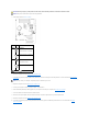
4 processor airflow shroud 5 primary hard drive bay 6 card fan 7 processor fan 8 lower 3.5-inch drive bay 9 upper 3.5-inch drive bay 10 lower 5.25-inch drive bay 11 upper 5.
technology) Cache 2MB or 4MB (depending on your configuration) Memory Type 533-MHz and 667-MHz ECC and non-ECC DDR2 SDRAM NOTE: Ensure that you do not mix ECC and non-ECC memory. NOTE: Your computer does not support registered or buffered memory.
Hard drive integrated serial ATA (4), with RAID 0/1/5/10 and command queuing integrated ATA-100 (1 channel) Expansion Bus Bus type Bus speed three PCI 2.2 one PCI Express one PCI Express one PCI Express eight USB 2.
Video VGA or DVI connector on graphic card Network adapter RJ45 connector PS/2 (keyboard and mouse) two 6-pin mini-DIN USB two front-panel, one internal, and five back-panel USB 2.
Environmental Temperature: Operating 10° to 35°C (50° to 95°F) Storage –40° to 65°C (–40° to 149°F) Relative humidity 20% to 80% (noncondensing) Maximum vibration: Operating 0.25 G at 3 to 200 Hz at 0.5 octave/min Storage 0.5 G at 3 to 200 Hz at 1 octave/min Maximum shock: Operating bottom half-sine pulse with a change in velocity of 50.8 cm/sec (20 inches/sec) Storage 27-G faired square wave with a velocity change of 508 cm/sec (200 inches/sec) Altitude: Operating –15.
3. Blow carefully into the ball cage to dislodge dust and lint. 4. If the rollers inside the ball cage are dirty, clean the rollers with a cotton swab moistened lightly with isopropyl alcohol. 5. Recenter the rollers in their channels if they are misaligned. Ensure that fluff from the swab is not left on the rollers. 6. Replace the ball and retainer ring, and turn the retainer ring clockwise until it clicks into place. Floppy Drive NOTICE: Do not attempt to clean drive heads with a swab.
Back to Contents Page Obtaining Assistance Dell Precision™ Workstation 390 User's Guide Online Services AutoTech Service Automated Order-Status Service Support Service Problems With Your Order Product Information Returning Items for Warranty Repair or Credit Before You Call Contacting Dell CAUTION: If you need to remove the computer covers, first disconnect the computer power and modem cables from all electrical outlets. 1. Complete the procedures in Solving Problems. 2.
support.jp.dell.com (Japan only) support.euro.dell.com (Europe only) l Electronic Quote Service apmarketing@dell.com (Asian/Pacific countries only) sales_canada@dell.com (Canada only) AutoTech Service Dell's automated support service—AutoTech—provides recorded answers to the questions most frequently asked by Dell customers about their portable and desktop computers. When you call AutoTech, use your touch-tone telephone to select the subjects that correspond to your questions.
Before You Call NOTE: Have your Express Service Code ready when you call. The code helps Dell's automated-support telephone system direct your call more efficiently. You may also be asked for your Service Tag (located on the back or bottom of your computer). Remember to fill out the Diagnostics Checklist (see Diagnostics Checklist). If possible, turn on your computer before you call Dell for assistance and call from a telephone at or near the computer.
Technical Support Services Sales Aruba Australia (Sydney) International Access Code: 0011 General Support toll-free: 0-800-444-0724 0-810-444-3355 toll-free: 800-1578 Website: support.ap.dell.com E-mail: support.ap.dell.com/contactus Country Code: 61 City Code: 2 General Support 13DELL-133355 Website: support.euro.dell.com E-mail: tech_support_central_europe@dell.
Technical Support E-mail: cn_support@dell.com Customer Care E-mail: customer_cn@dell.
Country Code: 33 Fax Fax (calls from outside of France) City Codes: (1) (4) 0825 004 701 04 99 75 40 01 Corporate Technical Support Customer Care 0825 004 719 0825 338 339 Switchboard 01 55 94 71 00 Sales 01 55 94 71 00 Fax 01 55 94 71 01 Website: support.euro.dell.com E-mail: tech_support_central_europe@dell.
Website: support.euro.dell.com Home and Small Business Italy (Milan) International Access Code: 00 Country Code: 39 City Code: 02 Technical Support 02 577 826 90 Customer Care 02 696 821 14 Fax 02 696 821 13 Switchboard 02 696 821 12 Corporate Technical Support 02 577 826 90 Customer Care 02 577 825 55 Fax 02 575 035 30 Switchboard Jamaica General Support (dial from within Jamaica only) 02 577 821 1-800-682-3639 Website: support.jp.dell.
Corporate Sales toll-free: 1 800 888 213 001-877-384-8979 Customer Technical Support or 001-877-269-3383 50-81-8800 Mexico Sales or 01-800-888-3355 International Access Code: 00 001-877-384-8979 Country Code: 52 Customer Service or 001-877-269-3383 50-81-8800 Main or 01-800-888-3355 Montserrat General Support toll-free: 1-866-278-6822 Netherlands Antilles General Support 001-800-882-1519 Website: support.euro.dell.
Singapore (Singapore) Technical Support (Dimension, Inspiron, and Electronics and Accessories) toll-free: 1800 394 7430 International Access Code: 005 Technical Support (OptiPlex, Latitude, and Dell Precision) toll-free: 1800 394 7488 Country Code: 65 Customer Care Technical Support (PowerApp, PowerEdge, PowerConnect, and PowerVault) Transaction Sales Corporate Sales toll-free: 1800 394 7478 toll-free: 1 800 394 7430 (option 6) toll-free: 1 800 394 7412 toll-free: 1 800 394 7419 Website: support.
Corporate Sales toll-free: 00801 651 227 Website: support.ap.dell.
Back to Contents Page
Back to Contents Page Glossary Dell Precision™ Workstation 390 User's Guide Terms in this Glossary are provided for informational purposes only and may or may not describe features included with your particular computer. A AC — alternating current — The form of electricity that powers your computer when you plug the AC adapter power cable in to an electrical outlet.
CD-RW — CD rewritable — A rewritable version of a CD. Data can be written to a CD-RW disc, and then erased and written over (rewritten). CD-RW drive — A drive that can read CDs and write to CD-RW (rewritable CDs) and CD-R (recordable CDs) discs. You can write to CD-RW discs multiple times, but you can write to CD-R discs only once. CD-RW/DVD drive — A drive, sometimes referred to as a combo drive, that can read CDs and DVDs and write to CD-RW (rewritable CDs) and CD-R (recordable CDs) discs.
EMI — electromagnetic interference — Electrical interference caused by electromagnetic radiation. ENERGY STAR® — Environmental Protection Agency requirements that decrease the overall consumption of electricity. EPP — enhanced parallel port — A parallel connector design that provides bidirectional data transmission. ESD — electrostatic discharge — A rapid discharge of static electricity. ESD can damage integrated circuits found in computer and communications equipment.
I IC — integrated circuit — A semiconductor wafer, or chip, on which thousands or millions of tiny electronic components are fabricated for use in computer, audio, and video equipment. IDE — integrated device electronics — An interface for mass storage devices in which the controller is integrated into the hard drive or CD drive. IEEE 1394 — Institute of Electrical and Electronics Engineers, Inc.
measured in MHz. Mini PCI — A standard for integrated peripheral devices with an emphasis on communications such as modems and NICs. A Mini PCI card is a small external card that is functionally equivalent to a standard PCI expansion card. Mini-Card — A small card designed for integrated peripherals, such as communication NICs. The Mini-Card is functionally equivalent to a standard PCI expansion card. modem — A device that allows your computer to communicate with other computers over analog telephone lines.
RAID — redundant array of independent disks — A method of providing data redundancy. Some common implementations of RAID include RAID 0, RAID 1, RAID 5, RAID 10, and RAID 50. RAM — random-access memory — The primary temporary storage area for program instructions and data. Any information stored in RAM is lost when you shut down your computer. readme file — A text file included with a software package or hardware product.
SXGA — super-extended graphics array — A video standard for video cards and controllers that supports resolutions up to 1280 x 1024. SXGA+ — super-extended graphics array plus — A video standard for video cards and controllers that supports resolutions up to 1400 x 1050. system board — The main circuit board in your computer. Also known as the motherboard. system setup — A utility that serves as an interface between the computer hardware and the operating system.
wireless routers to provide Internet access. write-protected — Files or media that cannot be changed. Use write-protection when you want to protect data from being changed or destroyed. To writeprotect a 3.5-inch floppy disk, slide its write-protect tab to the open position. WWAN — wireless wide area network. A wireless high-speed data network using cellular technology and covering a much larger geographic area than WLAN.
Back to Contents Page Copying CDs and DVDs Dell Precision™ Workstation 390 User's Guide How to Copy a CD or DVD Using Blank CDs and DVDs Helpful Tips NOTE: Ensure that you observe all copyright laws when creating CDs or DVDs. This section applies only to computers that have a CD-RW, DVD+/-RW, or CD-RW/DVD (combo) drive. NOTE: The types of CD or DVD drives offered by Dell may vary by country.
CD-R Yes Yes No CD-RW Yes Yes Yes DVD+R Yes Yes No DVD-R Yes Yes No DVD+RW Yes Yes Yes DVD-RW Yes Yes Yes DVD+R DL Yes Yes No DVD-R DL Maybe No No DVD-RAM Maybe No No Helpful Tips l Use Microsoft® Windows® Explorer to drag and drop files to a CD-R or CD-RW only after you start Roxio Creator Plus and open a Creator project. l Use CD-Rs to burn music CDs that you want to play in regular stereos. CD-RWs may not play in many home or car stereos.
Back to Contents Page Removing and Installing Parts Dell Precision™ Workstation 390 User's Guide Before You Begin Cards Recommended Tools Installing the Optional Speaker Turn Off Your Computer Processor Before Working Inside Your Computer Battery Removing the Computer Cover and Front Panel I/O Panel Chassis Intrusion Switch Power Supply Memory System Board Drives Replacing the Front Panel and Replacing the Computer Cover Before You Begin This chapter provides procedures for removing and ins
1. Turn off your computer. NOTICE: To disconnect a network cable, first unplug the cable from your computer and then unplug it from the network port or device. 2. Disconnect any telephone or telecommunication lines from the computer. 3. Disconnect your computer and all attached devices from their electrical outlets, and then press the power button to ground the system board.
7. Release the cover from the hinge tabs and set it aside in a secure location. Removing the Front Panel CAUTION: Before you begin any of the procedures in this section, follow the safety instructions in the Product Information Guide. CAUTION: To guard against electrical shock, always unplug your computer from the electrical outlet before removing the cover.
Replacing the Chassis Intrusion Switch 1. Gently slide the chassis intrusion switch into its slot and reconnect the cable to the system board. 2. Replace the computer cover. See Replacing the Computer Cover. 3. Attach the computer stand, if it is used. NOTICE: To connect a network cable, first plug the cable into the network port or device and then plug it into the computer. 4. Connect your computer and devices to electrical outlets, and turn them on. Resetting the Chassis Intrusion Detector 1.
NOTE: Always install memory modules in the order indicated on the system board. The recommended memory configurations are: ¡ A pair of matched memory modules installed in connectors DIMM_1 and DIMM_2 or ¡ l l l A pair of matched memory modules installed in connectors DIMM_1 and DIMM_2 and another matched pair installed in connectors DIMM_3 and DIMM_4 If you install mixed pairs of DDR2 memory that run at different speeds, the modules function at the slowest speed installed.
CAUTION: Before you begin any of the procedures in this section, follow the safety instructions in the Product Information Guide. CAUTION: To guard against electrical shock, always unplug your computer from the electrical outlet before opening the cover. NOTICE: To prevent static damage to components inside your computer, discharge static electricity from your body before you touch any of your computer's electronic components. You can do so by touching an unpainted metal surface on the computer. 1 1.
The computer should have changed the value of System Memory to reflect the newly installed memory. Verify the new total. If it is correct, skip to step 10. 9. If the memory total is incorrect, turn off and disconnect your computer and devices from their electrical outlets, remove the computer cover (see Removing the Computer Cover), and check the installed memory modules to ensure that they are seated properly in their sockets. Then repeat steps 6, 7, and 8. 10.
serial ATA hard drive) 4 secondary hard drive 5 primary hard drive 6 lower 3.5-inch drive bay (holds floppy drive or optional Media Card Reader) 7 upper 3.
Removing and Replacing an Upper Drive Bay Metal Shield To remove a metal shield from one of the upper drive bays: c. Grasp the metal shield by it's tab located in the center of the front surface. d. Pull the shield out by the tab in a straight motion to avoid tearing the tab from the shield. To replace a metal shield from one of the upper drive bays, align the shield so that it fits snugly with the drive bay and press in gently until it is flush with the surface of the bay.
1 power cable 2 SAS connector 3 SAS drive 4 SAS data cable 5 SAS connector 6 optional PCI Express SAS controller card Drive Cable Colors Device Color Hard drive blue cable Floppy drive black pull-tab CD/DVD drive orange pull-tab Hard Drive CAUTION: Before you begin any of the procedures in this section, follow the safety instructions in the Product Information Guide.
1 SATA0 connector 4 serial ATA cable 2 SATA1 connector 3 power cable To remove a SAS hard drive: a. Disconnect the power cable from the SAS drive. b. Remove the SAS connector from the hard drive. c. Disconnect the SAS cable from the SAS controller card. 1 SAS connector on SAS controller card 2 SAS connector on SAS controller card 4 hard drive in primary hard-drive bay 5 blue tabs (2 on each harddrive bracket) 3.
Installing a Hard Drive or Adding a Second Optional Hard Drive (Tower or Desktop Computer) 1. Unpack the replacement hard drive, and prepare it for installation. 2. Check the documentation for the hard drive to verify that the drive is configured for your computer. NOTE: If a hard-drive bracket is still installed in the inside of the hard-drive bay, remove the bracket before you install the new hard drive with the new or old hard-drive bracket. 3.
b. Connect the SAS connector to the hard drive. c. Connect the other end of the SAS cable to the SAS controller card. g. Ensure that all connectors are properly cabled and firmly seated. h. Replace the computer cover. See Replacing the Computer Cover. NOTICE: To connect a network cable, first plug the cable into the network port or device and then plug it into the computer. 9. Connect the computer and devices to electrical outlets, and turn them on.
6. Set the drive aside in a secure location. 7. If you are removing a hard drive that has a metal shield, and are not going to install a replacement drive in the drive bay, reinstall the shield in the empty bay (see About the Metal Shields Present in Some Drive Configurations). Then, install a drive-panel insert (see Replacing a Drive-Panel Insert). Installing an Optional Third Hard Drive (Tower Computer) NOTICE: Do not attempt to install an SAS hard drive in the lower 3.5-inch drive bay.
2. Disconnect the power cable from the back of the hard drive. 3. Disconnect the serial ATA cable from the back of the hard drive and from the SATA connector on the system board. 1 sliding-plate lever 2 optional fourth hard drive 4. Slide the sliding-plate lever to release the shoulder screw and slide the drive out of the lower 5.25-inch drive bay. 5. Set the drive aside in a secure location.
5. Connect the serial ATA cable to the back of the drive and to the SATA3 connector on the system board. Removing an Optional Third Hard Drive (Desktop Computer) 1. Remove the front panel. See Removing the Front Panel. 2. Disconnect the power cable from the back of the hard drive and from the power supply. 3. If you are removing a SATA drive, disconnect the serial ATA cable from the back of the hard drive and from the SATA connector on the system board.
empty bay (see About the Metal Shields Present in Some Drive Configurations). Then, install a drive-panel insert (see Replacing a Drive-Panel Insert). Installing an Optional Third Hard Drive (Desktop Computer) CAUTION: For configurations with three SAS hard drives, you must install an additional fan. See Installing an Additional Fan. 1. If you are installing a new drive, unpack the drive and prepare it for installation.
1 sliding-plate lever 2 hard-drive holder with hard drive NOTE: The optional third hard drive is located in the lower 5.25-inch drive bay for desktop computers. 6. Connect a power cable to the hard drive and to the power supply. 7. Connect the serial ATA cable to the back of the drive and to the SATA3 connector on the system board.
1. Follow the procedures in Before You Begin. 2. Remove the computer cover (see Removing the Computer Cover). NOTICE: When placing the fan in the computer, ensure that the cables of other components, such as the power supply, remain in their proper position. 1 fan slots (3) 2 fan release tab 4 fan connector on system board 5 power supply 3 fan cable 3. Place the fan flush with the side of the power supply and engage the fan hooks in the three fan slots in the side of the power supply. 4.
NOTICE: To prevent static damage to components inside your computer, discharge static electricity from your body before you touch any of your computer's electronic components. You can do so by touching an unpainted metal surface on the computer. Removing the Drive Panel (Tower Computer) 1. Follow the procedures in Before You Begin. 2. Remove the computer cover (see Removing the Computer Cover). 3. Remove the front panel. See Removing the Front Panel.
1. On the inside of the drive panel, pinch the two drive-panel insert release tabs together and pull the insert out and to the right just enough to release it from the drive panel. 2. Set the drive-panel insert aside in a secure location. Replacing a Drive-Panel Insert 1. Place the drive-panel insert tab into the drive-panel slot. 2. Pinch the drive-panel insert release tabs and press the drive panel insert into place.
CAUTION: To guard against electrical shock, always unplug your computer from the electrical outlet before opening the cover. NOTICE: To prevent static damage to components inside your computer, discharge static electricity from your body before you touch any of your computer's electronic components. You can do so by touching an unpainted metal surface on the computer.
Installing a Floppy Drive or Media Card Reader (Tower Computer) NOTICE: In a tower configuration with 4 hard drives, there can only be one floppy drive or Media Card Reader which must be installed in the lower 3.5inch drive bay. In this case, the 4th hard drive (which must be a SATA drive) will occupy the upper 3.5-inch drive bay. 1. Follow the procedures in Before You Begin. 2. Remove the computer cover (see Removing the Computer Cover). 3. Remove the front panel. See Removing the Front Panel. 4.
1 drive-conversion latch 4 floppy-drive connector (FLOPPY) 9. 2 power cable 3 floppy-drive cable Check all cable connections, and fold cables out of the way to provide airflow for the fan and cooling vents. 10. Replace the front panel. See Replacing the Front Panel. 11. Replace the computer cover. See Replacing the Computer Cover. NOTICE: To connect a network cable, first plug the cable in to the network port or device and then plug it in to the computer. 12.
1 power cable 2 floppy-drive cable 3 floppy-drive connector (FLOPPY) 6. Pull the desktop drive retention insert by the handle and set it aside in a safe place. 7. Slide the sliding-plate lever to the right to release the shoulder screw and slide the drive out of the 3.5- inch drive bay. 1 drive retention insert 2 sliding-plate lever 3 floppy drive Installing a Floppy Drive or Media Card Reader (Desktop Computer) 1. Follow the procedures in Before You Begin. 2.
1 drive 2 screws (2) 5. Gently slide the drive into place until you hear a click or feel the drive securely installed. 6. Attach the power and data cables to the floppy drive or Media Card Reader. 7. Connect the other end of the data cable to the system board connector labeled "FLOPPY" (for a floppy drive) or "FLEXBAY" (for a Media Card Reader). To locate system board connectors, see System Board Components. 1 power cable 2 floppy-drive cable 3 floppy-drive connector (FLOPPY) 8.
NOTICE: To prevent static damage to components inside your computer, discharge static electricity from your body before you touch any of your computer's electronic components. You can do so by touching an unpainted metal surface on the computer. Removing a CD/DVD Drive (Tower Computer) 1. Follow the procedures in Before You Begin. 2. Remove the computer cover (see Removing the Computer Cover). 3. Remove the front panel. See Removing the Front Panel. 4.
3. 4. Remove the front panel. See Removing the Front Panel. If you are installing a new drive, unpack the drive and prepare it for installation. Check the documentation that accompanied the drive to verify that the drive is configured for your computer. If you are installing an IDE drive, configure the drive for the cable select setting. 1 5.
1 2. Remove the computer cover (see Removing the Computer Cover). 3. Remove the front panel. See Removing the Front Panel. 4. Disconnect the power cable from the back of the drive and the CD/DVD-drive cable from the back of the drive and the system board. CD/DVD-drive cable 2 power cable 3 system-board CD/DVD- drive connector 5. Pull the drive retention insert out by the handle and set it aside in a safe place. 6. Slide the drive out and remove it from the drive bay.
1 3. Gently slide the drive into place until the drive securely clicks into position. 4. Connect the power cable to the drive, and connect the CD/DVD-drive cable to the drive and to the system board. CD/DVD-drive cable 2 power cable 3 system-board CD/DVD-drive connector 5. Check all cable connections, and fold cables out of the way to avoid blocking the fan and cooling vents. 6. Replace the front panel. See Replacing the Front Panel. 7. Replace the computer cover.
l Three PCI card slots l One PCI Express x16 card slot l One PCI Express x8 card slot (wired as x4) l One PCI Express x1 card slot PCI Cards If you are installing or replacing a PCI card, see Installing a PCI Card. If you are removing but not replacing a PCI card, see Removing a PCI Card. If you are replacing a card, remove the current driver for the card from the operating system.
1 release tab 4. 2 card retention mechanism 3 card retention door If your computer includes a card retention mechanism to secure the card in place from the top: a. Pivot the mechanism upward and gently press the release tab downward to release the mechanism from the two tab slots holding it in place. b. Set the retention mechanism aside in a secure location. 5. If you are installing a long card, repeat step 4 for the card retention mechanism near the system fan. 6.
1 11. card retention door 2 release tab Close the card retention door by snapping it into place to secure the card(s). NOTICE: Do not route card cables over or behind the cards. Cables routed over the cards can prevent the computer cover from closing properly or cause damage to the equipment. 12. Connect any cables that should be attached to the card. See the documentation for the card for information about the card's cable connections. 13.
b. 19. Connect the network cable to the network adapter cards connectors. Do not connect the network cable to the network connector on the back panel. Install any drivers required for the card as described in the card documentation. Removing a PCI Card 1. Follow the procedures in Before You Begin. 2. Remove the computer cover (see Removing the Computer Cover). 1 release tab 2 card retention door 4 alignment guide 5 filler bracket 3.
NOTICE: To connect a network cable, first plug the cable into the network adapter and then plug the cable into the computer. 7. Replace the computer cover, (see Replacing the Computer Cover), reconnect the computer and devices to electrical outlets, and then turn them on. 8. Uninstall the driver for the removed card. See the documentation that came with the card. 9. If you removed a sound card: 10. a.
1 release tab 4. 2 card retention mechanism 3 card retention door If your computer includes a card retention mechanism to secure the card in place from the top: a. Pivot the mechanism upward and gently press the release tab downward to release the mechanism from the two tab slots holding it in place. b. Set the retention mechanism aside in a secure location. 5. If you are installing a new card, remove the filler bracket to create a card-slot opening. Then, continue with step 7. 6.
1 alignment guide 2 bracket caught outside of slot 3 bracket within slot 4 alignment bar 5 fully seated card 6 not fully seated card 10. If you replaced a card that was already installed in the computer and you removed the retention mechanism, you may reinstall the retention mechanism. 11. Before replacing the card retention mechanism, ensure that: 12. 1 l The tops of all cards and filler brackets are flush with the alignment bar.
Removing a PCI Express Card 1. Follow the procedures in Before You Begin. 2. Remove the computer cover (see Removing the Computer Cover). 1 release tab 2 card retention door 4 alignment guide 5 filler bracket 3. 1 alignment bar Gently push the release tab on the card retention door from the inside to pivot the door open. Because the door is captive, it will remain in the open position. release tab 4.
NOTICE: To connect a network cable, first plug the cable into the network adapter and then plug the cable into the computer. 9. Replace the computer cover, (see Replacing the Computer Cover), reconnect the computer and devices to electrical outlets, and then turn them on. 10. Uninstall the driver for the removed card. See the documentation that came with the card. 11. If you removed a sound card: 12. a.
1 speaker (optional) 2 latch release tab 4 speaker cable 5. 3 speaker slots with tabs (3) 5 speaker connector on system board Replace the computer cover. See Replacing the Computer Cover. Processor CAUTION: Before you begin any of the procedures in this section, follow the safety instructions in the Product Information Guide. CAUTION: To guard against electrical shock, always unplug your computer from the electrical outlet before opening the cover.
1 heat-sink assembly 2 captive screw housing (2) NOTICE: If you are installing a processor upgrade kit from Dell, discard the original heat-sink assembly. If you are not installing a processor upgrade kit from Dell, reuse the original heat-sink assembly when you install your new processor. 5. Open the processor cover by sliding the release lever from under the center cover latch on the socket. Then, pull the lever back to release the processor.
4. If the release lever on the socket is not fully extended, move it to that position. 5. Orient the front and rear alignment notches on the processor with the front and rear alignment notches on the socket. 6. Align the pin-1 corners of the processor and socket.
1 heat-sink assembly 11. 2 heat-sink assembly bracket 3 captive screw housing (2) Replace the computer cover. See Replacing the Computer Cover. NOTICE: To connect a network cable, first plug the cable into the network port or device and then plug the cable into the computer. 12. Connect your computer and devices to electrical outlets, and turn them on. Battery CAUTION: Before you begin any of the procedures in this section, follow the safety instructions in the Product Information Guide.
2. Remove the computer cover (see Removing the Computer Cover). 3. Locate the battery socket. NOTICE: If you pry the battery out of its socket with a blunt object, be careful not to touch the system board with the object. Ensure that the object is inserted between the battery and the socket before you attempt to pry out the battery. Otherwise, you may damage the system board by prying off the socket or by breaking circuit traces on the system board.
CAUTION: Before you begin any of the procedures in this section, follow the safety instructions in the Product Information Guide. CAUTION: To guard against electrical shock, always unplug your computer from the electrical outlet before opening the cover. NOTICE: To prevent static damage to components inside your computer, discharge static electricity from your body before you touch any of your computer's electronic components. You can do so by touching an unpainted metal surface on the computer.
1 heat-sink assembly 2 captive screw housing (2) 5. Place the heat-sink assembly on its side in a safe place. 6. Disconnect the system fan cable from the system board. 1 fan release lever 2 fan 7. Lift the fan release lever and slide the fan toward the back of the computer to release it from the bottom and remove it from the computer. 8. Disconnect the control-panel cable from the I/O panel connector by pulling with the cable loop. 9. Remove the front panel. See Removing the Front Panel.
1 I/O panel 2 mounting screw 14. Remove the mounting screw from the I/O panel. 15. Remove the I/O panel from the computer. Replacing the I/O Panel Follow the removal procedure in reverse order, ensuring that the tabs on the top panel, bottom panel, and front panel are secure. Power Supply CAUTION: Before performing any of the procedures in this section, follow the safety instructions in the Product Information Guide.
1 power supply screws (4) 5. Slide the power supply toward the front of the computer by approximately one inch. 6. Lift the power supply out of the computer. Replacing the Power Supply 1. Slide the power supply into place. 2. Replace the four screws that secure the power supply to the back of the computer chassis. 3. Reconnect the DC power cables. 4. On the desktop computer, reattach the power cables to the side of the hard drive. 5.
3. Remove the front panel. See Removing the Front Panel. 4. Remove any components that restrict access to the system board. 5. Disconnect all cables from the system board. 6. Before you remove the existing system board assembly, visually compare the replacement system board to the existing system board to make sure that you have the correct part. 7. Remove the system board screws. 1 system board 2 screws 8.
3. Orient the replacement board by aligning the notches on the bottom of the board with the tabs on the computer. 4. Slide the system board assembly toward the back of the computer until the assembly clicks into position. 5. Replace any components and cables that you removed from the system board. 6. Reconnect all cables to their connectors at the back of the computer. 7. Replace the computer cover. See Replacing the Computer Cover.
Back to Contents Page Changing Between Tower and Desktop Orientations Dell Precision™ Workstation 390 User's Guide Drive-Panel Inserts Switching Drive Orientations Drive Panel CAUTION: Before you begin any of the procedures in this section, follow the safety instructions in the Product Information Guide. CAUTION: To guard against electrical shock, always unplug your computer from the electrical outlet before opening the cover.
Installing Drive-Panel Inserts in the Desktop Computer Drive Panel 1. Place the drive-panel insert tab into the drive-panel slot. 2. Pinch the drive-panel insert release tabs and press the drive panel insert into place. 1 drive panel 2 drive-panel insert 3 drive-panel insert release tabs (2) 4 drive-panel insert tab in tab slot 3. Ensure that the drive-panel insert is correctly seated in the drive panel. Switching Drive Orientations NOTE: The tower computer supports one more 3.
1 sliding plate 2 sliding-plate lever 3 drive panel Replacing the Drive Panel (Tower Computer) 1. Align the drive-panel tabs with the side-door hinges. 1 sliding plate 4 drive panel tabs 2 sliding-plate lever 3 drive panel 2. Rotate the drive panel toward the computer until it snaps into place on the front panel. 3. To rotate the Dell™ badge on the front panel, place fingers around the outside of the badge, press in, and turn the badge.
NOTE: The desktop drive panel is an optional item that can be purchased separately if your original system is a tower computer. 1. 1 Slide the sliding-plate lever to the right, pivot the drive panel outward, and lift to remove the panel. sliding plate 2 sliding-plate lever 3 drive panel Replacing the Drive Panel (Desktop Computer) 1. Align the drive-panel tabs with the side-door hinges. 1 sliding plate 4 drive-panel tabs 2 sliding-plate lever 3 drive panel 2.
7. Verify that your computer works correctly by running the Dell Diagnostics (see Dell Diagnostics).
Back to Contents Page Solving Problems Dell Precision™ Workstation 390 User's Guide Troubleshooting Tips Memory Problems Battery Problems Mouse Problems Card Problems Network Problems Card Fan Problems Power Problems Drive Problems Printer Problems E-Mail, Modem, and Internet Problems Serial or Parallel Device Problems IEEE 1394 Device Problems Sound and Speaker Problems Keyboard Problems Video and Monitor Problems Lockups and Software Problems Troubleshooting Tips Follow these tips when y
Test the graphics card — 1. Turn off the computer and devices, disconnect them from their electrical outlets, wait 10 to 20 seconds, and then remove the remove the computer cover (see Removing the Computer Cover). Remove all cards except the graphics card. See Removing a PCI Card. 2. If your primary hard drive is connected to a drive controller card and not to one of the system board IDE connectors, leave the drive controller card installed in the computer. 3. 4.
Check for Software and Hardware Conflicts Run the Dell Diagnostics (see Dell Diagnostics) CD and DVD drive problems NOTE: High-speed CD or DVD drive vibration is normal and may cause noise, which does not indicate a defect in the drive or the CD or DVD. NOTE: Because of different regions worldwide and different disc formats, not all DVD titles work in all DVD drives. Adjust the Windows volume control — l l l Click the speaker icon in the lower-right corner of your screen.
NOTE: Connect the modem to an analog telephone jack only. The modem does not operate while it is connected to a digital telephone network. Check the Microsoft Outlook® Express Security Settings — If you cannot open your e-mail attachments: 1. 2. In Outlook Express, click Tools, click Options, and then click Security. Click Do not allow attachments to remove the checkmark.
If you have problems with a Dell-provided IEEE 1394 device — If you have problems with an IEEE 1394 device not provided by Dell — Contact Dell (see Contacting Dell) or the IEEE 1394 device manufacturer. Keyboard Problems CAUTION: Before you begin any of the procedures in this section, follow the safety instructions in the Product Information Guide. Check the keyboard cable — l l l l Ensure that the keyboard cable is firmly connected to the computer.
1. 2. 3. 4. Press simultaneously. Click Applications. Click the program that is no longer responding. Click End Task. A program crashes repeatedly NOTE: Software usually includes installation instructions in its documentation or on a floppy disk or CD. Check the software documentation — If necessary, uninstall and then reinstall the program.
Memory Problems Fill out the Diagnostics Checklist as you complete these checks. CAUTION: Before you begin any of the procedures in this section, follow the safety instructions in the Product Information Guide. CAUTION: To guard against electrical shock, always unplug your computer from the electrical outlet before opening the cover.
Fill out the Diagnostics Checklist as you complete these checks. CAUTION: Before you begin any of the procedures in this section, follow the safety instructions in the Product Information Guide. Check the network cable connector — Ensure that the network cable is firmly inserted into both the network connector on the back of the computer and the network jack. Check the network lights on the back of the computer — No light indicates that no network communication exists. Replace the network cable.
l Multiple power strips connected to the same electrical outlet Printer Problems Fill out the Diagnostics Checklist as you complete these checks. CAUTION: Before you begin any of the procedures in this section, follow the safety instructions in the Product Information Guide. NOTE: If you need technical assistance for your printer, contact the printer's manufacturer. Check the printer documentation — See the printer documentation for setup and troubleshooting information.
No sound from speakers NOTE: The volume control in some MP3 players overrides the Windows volume setting. If you have been listening to MP3 songs, ensure that you did not turn the player volume down or off. Check the speaker cable connections — Ensure that the speakers are connected as shown on the setup diagram supplied with the speakers. If you purchased a sound card, ensure that the speakers are connected to the card.
Adjust the Windows volume control — Click or double-click the speaker icon in the lower-right corner of your screen. Ensure that the volume is turned up and that the sound is not muted. Video and Monitor Problems Fill out the Diagnostics Checklist as you complete these checks. CAUTION: Before you begin any of the procedures in this section, follow the safety instructions in the Product Information Guide. If the screen is blank NOTE: See the monitor documentation for troubleshooting procedures.
Back to Contents Page
Back to Contents Page Dell Precision™ Workstation 390 User's Guide NOTE: A NOTE indicates important information that helps you make better use of your computer. NOTICE: A NOTICE indicates either potential damage to hardware or loss of data and tells you how to avoid the problem. CAUTION: A CAUTION indicates a potential for property damage, personal injury, or death. For a complete list of abbreviations and acronyms, see the Glossary.
Back to Contents Page Tools to Help Solve Problems Dell Precision™ Workstation 390 User's Guide Diagnostic Lights Beep Codes Error Messages Dell Diagnostics Drivers Using Microsoft® Windows® XP System Restore Resolving Software and Hardware Incompatibilities Reinstalling Microsoft® Windows® XP Diagnostic Lights CAUTION: Before you begin any of the procedures in this section, follow the safety instructions in the Product Information Guide.
NOTE: If the problem persists, contact Dell (see Contacting Dell). A possible graphics card failure has occurred. 1. 2. 3. If the computer has a graphics card, remove the card, reinstall it, and then restart the computer. If the problem still exists, install a graphics card that you know works and restart the computer. If the problem persists or the computer has integrated graphics, contact Dell (see Contacting Dell).
Beep Codes Your computer might emit a series of beeps during start-up if the monitor cannot display errors or problems. This series of beeps, called a beep code, identifies a problem. One possible beep code (code 1-3-1) consists of one beep, a burst of three beeps, and then one beep. This beep code tells you that the computer encountered a memory problem. If your computer beeps during start-up: 1. Write down the beep code on the Diagnostics Checklist. 2.
If the message is not listed, see the documentation for the operating system or the program that was running when the message appeared. A filename cannot contain any of the following characters: \ / : * ? " < > | — Do not use these characters in filenames. A required .DLL file was not found — The program that you are trying to open is missing an essential file. To remove and then reinstall the program: 1. 2. 3. 4. Click the Start button, click Control Panel, and then click Add or Remove Programs.
Diskette subsystem reset failed — Dell Diagnostics (see Dell Diagnostics). Diskette write protected — Slide the write-protect notch to the open position. Drive not ready — Put a floppy disk in the drive. Gate A20 failure — See Lockups and Software Problems. Hard-disk configuration error — Hard-disk controller failure — Hard-disk drive failure — Hard-disk drive failure — See Drive Problems. Insert bootable media — Insert a bootable floppy disk or CD.
If the message continues to appear after you ensure that the information in system setup is correct, see your operating system documentation for reinstallation information. No timer tick interrupt — Run the Dell Diagnostics (see Dell Diagnostics). Non-system disk or disk error — Replace the floppy disk with one that has a bootable operating system or remove the floppy disk from drive A and restart the computer. Not a boot diskette — Insert a bootable floppy disk and restart your computer.
Unexpected interrupt in protected mode — Run the Dell Diagnostics (see Dell Diagnostics). WARNING: Dell's Disk Monitoring System has detected that drive [0/1] on the [primary/secondary] IDE controller is operating outside of normal specifications.
2. Shut down the computer (see Turn Off Your Computer). When the DELL logo appears, press immediately. If you wait too long and the Windows logo appears, continue to wait until you see the Windows desktop. Then shut down the computer (see Turn Off Your Computer), and try again. NOTE: The next steps change the boot sequence for one time only. On the next start-up, the computer boots according to the devices specified in system setup. 3.
What Is a Driver? A driver is a program that controls a device such as a printer, mouse, or keyboard. All devices require a driver program. A driver acts like a translator between the device and any other programs that use the device. Each device has its own set of specialized commands that only its driver recognizes. Dell ships your computer to you with required drivers already installed—no further installation or configuration is needed.
7. Click the Drivers tab. 8. Click Roll Back Driver. If Device Driver Rollback does not resolve the problem, then use System Restore (see Restoring the Computer to an Earlier Operating State)to return your computer to the operating state that existed before you installed the new driver. Using the Drivers and Utilities CD If using Device Driver Rollback or System Restore does not resolve the problem, then reinstall the driver from the Drivers and Utilities CD (also known as the Resource CD).
The Select a Restore Point screen provides a calendar that allows you to see and select restore points. All calendar dates with available restore points appear in boldface type. 4. Select a restore point and click Next. If a calendar date has only one restore point, then that restore point is automatically selected. If two or more restore points are available, click the restore point that you prefer. 5. Click Next.
NOTICE: You must use Windows XP Service Pack 1 (SP1) or later when you reinstall Windows XP. Before You Begin If you are considering reinstalling the Windows XP operating system to correct a problem with a newly installed driver, first try using Windows XP Device Driver Rollback (see Using Windows XP Device Driver Rollback).
NOTE: The time required to complete the setup depends on the size of the hard drive and the speed of your computer. NOTICE: Do not press any key when the following message appears: Press any key to boot from the CD. 6. When the Regional and Language Options screen appears, select the settings for your location and click Next. 7. Enter your name and organization (optional) in the Personalize Your Software screen, and click Next. 8.
Back to Contents Page Dell Precision™ Workstation 390 User's Guide NOTE: A NOTE indicates important information that helps you make better use of your computer. NOTICE: A NOTICE indicates either potential damage to hardware or loss of data and tells you how to avoid the problem. CAUTION: A CAUTION indicates a potential for property damage, personal injury, or death. For a complete list of abbreviations and acronyms, see the Glossary.