
Users Guide


Hardware Configuration Features B-15
86%&RQQHFWRUV
Your system contains two Universal Serial Bus (USB) connectors for attaching USB-
compliant devices. USB devices are typically peripherals such as keyboards, mice,
printers, and computer speakers.
&$87,21 'R QRW DWWDFK D 86% GHYLFH RU D FRPELQDWLRQ RI 86% GHYLFHV
WKDW GUDZ D PD[LPXP FXUUHQW RYHU PLOOLDPSHUHV P$ SHU FKD QQHO
RU YROWV 9 $WWDFKLQJ GHYLFHV WKDW H[ FHHG WKLV WKUHVKROG PD\ FDXVH WKH
86% SRUWV WR VKXW GRZQ 6HH WKH GRFXPHQWDWLRQ WKDW DF FRPSDQLHG WKH 86%
GHYLFHV IRU WKHLU PD[LPXP FXUUHQW UDWLQJV
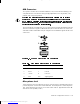
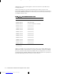
If you reconfigure your hardware, you may need pin number and signal information for
the USB connectors. Figure B-9 illustrates the pin numbers for the USB connectors,
and Table B-8 lists and defines the pin assignments and interface signals for the USB
connectors.
)LJXUH % 3LQ 1XPEHUV I RU WKH 86% &RQQHFWRUV
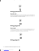
0LFURSKRQH-DFN
The microphone jack (see Figure B-10) can be used to attach a standard personal com-
puter microphone. Connect the audio cable from the microphone to the microphone
jack. The microphone input is a mono source with maximum signal levels of 89 milli-
volts root mean squared (mVrms).
7DEOH % 3LQ $VVLJQPHQWV IRU WKH 86% &RQQHFWRUV
3LQ 6LJQDO ,2 'HILQLWLRQ
1 Vcc N/A Supply voltage
2DATA I Data in
3+DATA O Data out
4 GND N/A Signal ground
1
2
USB
1 4
1 4
23205BK0.BK : 23205AB0.FM Page 15 Wednesday, March 18, 1998 1:51 PM
Downloaded from www.Manualslib.com manuals search engine