
Owners Manual
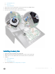
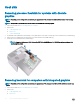
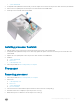
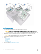
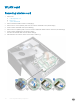
Table Of Contents
- Precision 5720 All-in-One Owner’s Manual
- Working on your computer
- Removing and installing components
- USB dongle-bay cover
- Back cover
- Memory module
- Hard drive
- System board shield
- M.2 PCIe SSD
- Memory fan
- Heat sink
- Processor
- Coin cell battery
- WLAN card
- Stand
- System fan
- Power supply unit
- Inner frame
- Built-in self test button
- Microphone
- I/O panel
- USB-dongle port
- Diagnostic light and button board
- Drive cage
- Converter board
- Speaker
- Power button board
- Media card reader
- Camera
- System board
- Display assembly
- Middle frame
- Speaker bezel
- Display panel
- Technology and components
- System setup
- Software
- Troubleshooting
- Technical specifications
- System specifications
- Memory specifications
- Video specifications
- Audio specifications
- Communication specifications
- Connectors
- Display specifications
- Storage specifications
- Port and connector specifications
- Power specifications
- Camera specifications
- Stand specifications
- Physical specifications
- Environmental specifications
- Contacting Dell
a USB dongle-bay cover
b back cover
c system-board shield
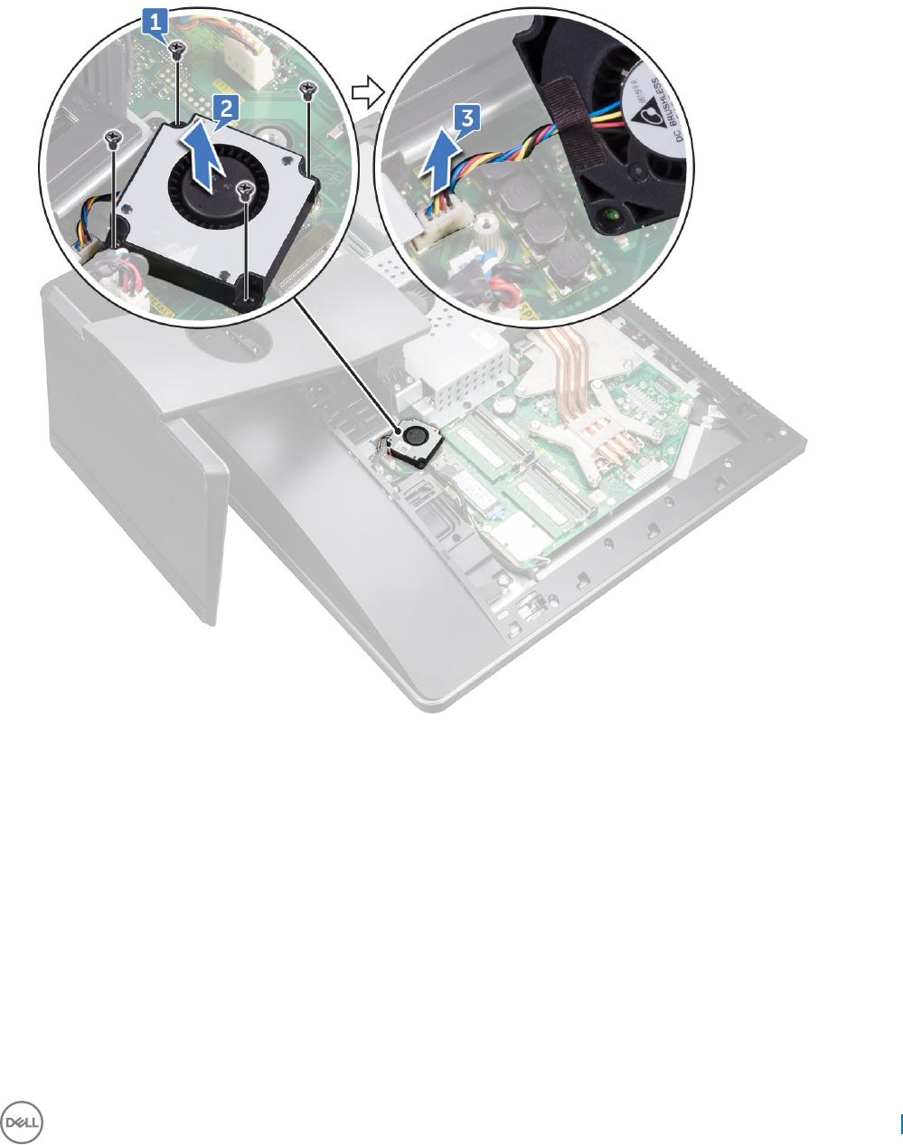
3 Remove the four screws (M2X3) that secure the memory fan to the middle frame [1].
4 Gently lift the memory fan from the system board [2].
5 Disconnect the memory fan cable from the system board [3].
Installing memory fan
1 Connect the memory fan cable to the system board.
2 Align the screw holes on the memory fan with the screw holes on the system board.
3 Replace the four screws (M2X3) that secure the memory fan to the system board.
4 Install the:
a system-board shield
b back cover
c USB dongle-bay cover
5 Follow the procedure in After working inside your computer.
Removing and installing components
21