Dell Precision T1600 Service Manual Regulatory Model: D09M Regulatory Type: D09M001
Notes, Cautions, and Warnings NOTE: A NOTE indicates important information that helps you make better use of your computer. CAUTION: A CAUTION indicates either potential damage to hardware or loss of data and tells you how to avoid the problem. WARNING: A WARNING indicates a potential for property damage, personal injury, or death. © 2013 Dell Inc. All Rights Reserved.
Contents 1 Working on Your Computer...................................................................... 7 Before Working Inside Your Computer............................................................................. 7 Recommended Tools.........................................................................................................8 Turning Off Your Computer................................................................................................8 After Working Inside Your Computer........
Removing The Intrusion Switch...................................................................................... 25 Installing The Intrusion Switch....................................................................................... 26 9 Speaker...................................................................................................... 27 Removing The Internal Speaker......................................................................................27 Installing The Internal Speaker......
17 System Board..........................................................................................51 Removing The System Board.......................................................................................... 51 Installing The System Board........................................................................................... 52 18 System Setup.......................................................................................... 53 System Setup.........................................
Working on Your Computer 1 Before Working Inside Your Computer Use the following safety guidelines to help protect your computer from potential damage and to help to ensure your personal safety. Unless otherwise noted, each procedure included in this document assumes that the following conditions exist: • • You have read the safety information that shipped with your computer. A component can be replaced or--if purchased separately--installed by performing the removal procedure in reverse order.
NOTE: The color of your computer and certain components may appear differently than shown in this document. To avoid damaging your computer, perform the following steps before you begin working inside the computer. 1. Ensure that your work surface is flat and clean to prevent the computer cover from being scratched. 2. Turn off your computer (see Turning Off Your Computer). CAUTION: To disconnect a network cable, first unplug the cable from your computer and then unplug the cable from the network device.
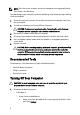
b. * – Select the and then select Shut down Using a mouse: a. Point to upper-right corner of the screen and click Settings. b. Click the and select Shut down. In Windows 7: 1. Click Start . 2. Click Shut Down. or 2. 1. Click Start 2. Click the arrow in the lower-right corner of the Start menu as shown below, and then click Shut Down.. . Ensure that the computer and all attached devices are turned off.
Cover 2 Removing The Cover 1. Follow the procedures in Before Working Inside Your Computer. 2. Pull up the cover release latch at the side of the computer. 3. Lift the cover upward to a 45—degree angle and remove it from the computer.
Installing The Cover 1. Place the cover on the computer. 2. Press down on the cover till it clicks into place. 3. Follow the procedures in After Working Inside Your Computer.
Front Bezel 3 Removing The Front Bezel 1. Follow the procedures in Before Working Inside Your Computer. 2. Remove the Cover. 3. Gently pry the front bezel retention clips away from the chassis located at the side edge of front bezel. 4. Rotate the bezel away from the computer to release the hooks on the opposite edge of the bezel from the chassis.
Installing The Front Bezel 1. Insert the hooks along the bottom edge of the front bezel into the slots on the chassis front. 2. Rotate the bezel toward the computer to engage the four front-bezel retention clips until they click into place. 3. Install the Cover. 4. Follow the procedures in After Working Inside Your Computer.
Expansion Card Tab 4 Removing The Expansion Card 1. Follow the procedures in Before Working Inside Your Computer. 2. Remove the Cover. 3. Push the release tab on the card-retention latch outward. 4. Gently pull the release lever away from the PCIe x16 card until you release the securing tab from the dent in the card. Then, ease the card up and out of its connector and remove it from the system. 5. Lift the PCIe x1 expansion card (if any) up and out of its connector and remove it from the system.
6. Lift the PCI expansion card (if any) up and out of its connector and remove it from the system. 7. Lift the PCI x4 expansion card (if any) up and out of its connector and remove it from the system.
Installing The Expansion Card 1. Insert the PCIe x4 card into the connector on the system board and press down until it is securely in place. 2. Insert the PCIe card into the connector on the system board and press down until it is securely in place. 3. Insert the PCIe x1 card into the connector on the system board and press down until it is securely in place. 4. Insert the PCIe x16 card into the connector on the system board and press down until it is securely in place. 5.
Optical Drive 5 Removing The Optical Drive 1. Follow the procedures in Before Working Inside Your Computer. 2. Remove the Cover. 3. Remove the Front Bezel. 4. Remove the data cable(1) and power cable(2) from the back of the optical drive. 5. Slide down the optical drive latch and then push the optical drive from the back toward the front of the computer. 6. Repeat steps four and five to remove the second optical drive (if available).
Installing The Optical Drive Installing The Optical Drive 1. Slide up the optical drive latch and then push the optical drive from the front toward the back of the computer. 2. Connect the data cable and power cable to the back of the optical drive. 3. Install the Front Bezel. 4. Install the Cover. 5. Follow the procedures in After Working Inside Your Computer.
Hard Drive 6 Removing The Hard Drive 1. Follow the procedures in Before Working Inside Your Computer. 2. Remove the Cover. 3. Remove the data cable(1) and power cable(2) from the back of the hard drive. 4. Press both blue securing-bracket tabs inward and lift the hard drive bracket out of the bay. 5. Flex the hard drive bracket and then remove the hard drive from the bracket.
6. Repeat the preceding steps for the second hard drive, if available. Related Links Installing the Hard Drive Installing The Hard Drive 1. Flex the hard drive bracket and then insert the hard drive into the bracket. 2. Press both blue securing-bracket tabs inward and slide the hard drive bracket into the bay in the chassis. 3. Connect the data cable and power cable to the back of the hard drive. 4. Install the Cover. 5. Follow the procedures in After Working Inside Your Computer.
Memory 7 Removing The Memory 1. Follow the procedures in Before Working Inside Your Computer. 2. Remove the Cover. 3. Press down on the memory retaining tabs on each side of the memory modules. 4. Lift the memory modules out of the connectors on the system board.
Installing The Memory 1. Insert the memory modules into the connectors on the system board. Install the memory in the order of A1 > B1 > A2 > B2. 2. Press down on the memory modules until the release tabs spring back to secure them in place. 3. Install the Cover. 4. Follow the procedures in After Working Inside Your Computer.
Chassis Intrusion Switch 8 Removing The Intrusion Switch 1. Follow the procedures in Before Working Inside Your Computer. 2. Remove the Cover. 3. Disconnect the intrusion cable from system board. 4. Slide the intrusion switch toward the chassis bottom and remove it from the chassis.
Installing The Intrusion Switch 1. Insert the Intrusion Switch into the chassis rear and slide it toward the chassis top to secure it. 2. Connect the intrusion cable to the system board. 3. Install the Cover. 4. Follow the procedures in After Working Inside Your Computer.
Speaker 9 Removing The Internal Speaker 1. Follow the procedures in Before Working Inside Your Computer. 2. Remove the Cover. 3. Disconnect the speaker cable from the system board. 4. Unthread the internal speaker cable from the chassis clip. 5. Press down the speaker-securing tab and slide the speaker upwards to remove.
Related Links Installing the Internal Speaker Installing The Internal Speaker 1. Press the speaker-securing tab and slide the speaker downward to secure it. 2. Thread the internal speaker cable into the chassis clip. 3. Connect the speaker cable to the system board. 4. Install the Cover. 5. Follow the procedures in After Working Inside Your Computer.
Processor 10 Removing The Heat Sink And Processor 1. Follow the procedures in Before Working Inside Your Computer. 2. Remove the Cover. 3. Disconnect the heat sink/fan assembly cable from the system board. 4. Use a Phillips screwdriver to loosen the captive screws securing the heat sink/fan assembly to the system board. 5. Lift the heat sink/fan assembly upward gently, and remove it from the system. Lay the assembly with the fan facing downward, and with the thermal grease facing upward.
6. Press the release lever down and then move it outward to release it from the retention hook that secures it. 7. Lift the processor cover. 8. Lift the processor to remove it from the socket and place it in antistatic packaging.
Related Links Installing the Heat Sink and Processor Installing The Heat Sink And Processor 1. Insert the processor into the processor socket. Ensure the processor is properly seated. 2. Gently lower the processor cover. 3. Press the release lever down and then move it inward to secure it with the retention hook. 4. Place the heat sink/fan assembly into the chassis. 5. Use a Phillips screwdriver to tighten the captive screws securing the heat sink/fan assembly to the system board. 6.
Coin-Cell Battery 11 Removing The Coin-Cell Battery 1. Follow the procedures in Before Working Inside Your Computer. 2. Remove the Cover. 3. Carefully press the release latch away from the battery to allow the battery to pop up from the socket. 4. Lift the coin-cell battery out of the computer.
Installing The Coin-Cell Battery 1. Place the coin cell battery into the slot on the system board. 2. Press the coin cell battery downward until the release latch springs back into place and secures it. 3. Install the Cover. 4. Follow the procedures in After Working Inside Your Computer.
Power-Switch Cable 12 Removing The Power Switch Cable 1. Follow the procedures in Before Working Inside Your Computer. 2. Remove the Cover. 3. Remove the Front Bezel. 4. Remove the Optical Drive. 5. Disconnect the power switch cable from the system board. 6. Unthread the power switch cable from the chassis clips. 7. Unthread the power switch cable from the chassis clip.
8. Gently pry the power switch cable free. 9. Slide the power switch cable out through the front of the computer. Related Links Installing the Power Switch Cable Installing The Power Switch Cable 1. Slide the power switch cable in through the front of the computer. 2. Secure the power switch cable to the chassis.
3. Thread the power switch cable into the chassis clips. 4. Connect the power switch cable to the system board. 5. Install the Optical Drive. 6. Install the Front Bezel. 7. Install the Cover. 8. Follow the procedures in After Working Inside Your Computer.
Front Thermal Sensor 13 Removing The Front Thermal Sensor 1. Follow the procedures in Before Working Inside Your Computer. 2. Remove the Cover. 3. Disconnect the thermal sensor cable from the system board. 4. Unthread the thermal sensor cable from the chassis clip. 5. Gently pry the thermal sensor away from the chassis front and remove.
Related Links Installing the Front Thermal Sensor Installing The Front Thermal Sensor 1. Gently secure the thermal sensor to the chassis front. 2. Thread the thermal sensor cable into the chassis clips. 3. Connect the thermal sensor cable to the system board. 4. Install the Cover. 5. Follow the procedures in After Working Inside Your Computer.
System Fan 14 Removing The System Fan 1. Follow the procedures in Before Working Inside Your Computer. 2. Remove the cover. 3. Disconnect the chassis fan cable from the system board. 4. Pry and remove the system fan away from the four grommets securing it to the back of the computer.
Installing The System Fan 1. Place the chassis fan in the chassis. 2. Pass the four grommets through the chassis and slide outward along the groove to secure in place. 3. Connect the fan cable to the system board. 4. Install the Cover. 5. Follow the procedures in After Working Inside Your Computer.
Input/Output Panel 15 Removing The Input/Output Panel 1. Follow the procedures in Before Working Inside Your Computer. 2. Remove the Cover. 3. Remove the Front Bezel. 4. Disconnect the Input/output panel and FlyWire cable from the system board. 5. Unthread the I/O Panel and FlyWire cable from the clip on the computer. 6. Remove the screw that secures the I/O panel to the computer.
7. Slide the I/O panel towards the left of the computer to release it. 8. Remove the I/O panel by routing the cable through the front of the computer.
Installing The Input/Output Panel 1. Insert the Input/Output Board into the slot on the chassis front. 2. Slide the Input/Output Board towards the right of the computer to secure to the chassis. 3. Use a Phillips screwdriver to tighten the single screw securing the Input/Output Board to the chassis. 4. Thread the Input/Output Board/FlyWire cable into the chassis clip. 5. Connect the Input/Output Board/FlyWire cable to the system board. 6. Install the Front Bezel. 7. Install the Cover. 8.
Power Supply 16 Removing The Power Supply 1. Follow the procedures in Before Working Inside Your Computer. 2. Remove the Cover. 3. Disconnect the power cables connected to the hard drive(s) and optical drive(s). 4. Unthread the power cables from the clips in the computer. 5. Disconnect the 24-pin power cable from the system board.
6. Disconnect the 4-pin power cable from the system board. 7. Remove the four screws securing the power supply to the back of the computer. 8. Push in on the blue release tab beside the power supply (1), and slide the power supply towards the front of the computer (2).
9. Lift the power supply out of the computer. Related Links Installing the Power Supply Installing The Power Supply 1. Place the power supply in the chassis and slide towards the back of the system to secure it. 2. Use a Phillips screwdriver to tighten the screws securing the power supply to the back of the computer. 3. Connect the 4-pin power cable to the system board. 4. Connect the 24-pin power cable to the system board. 5. Thread the power cables into the chassis clips. 6.
System Board 17 Removing The System Board 1. Follow the procedures in Before Working Inside Your Computer. 2. Remove the Cover. 3. Remove the Front Bezel. 4. Remove the Expansion Card. 5. Remove the heat sink and processor. 6. Disconnect all the cables connected to the system board. 7. Remove the screws that secure the system board to the computer. 8. Slide the system board towards the front of the computer.
9. Carefully tilt the system board to 45–degrees, and then lift the system board out of the computer. Related Links Installing the System Board Installing The System Board 1. Align the system board to the port connectors on the rear of the chassis and place the system board in the chassis. 2. Tighten the screws securing the system board to the chassis. 3. Connect the cables to the system board. 4. Install the Heat sink and Processor. 5. Install the Expansion Card. 6. Install the Front Bezel.
18 System Setup System Setup The system offers the following options: • Access System Setup by pressing • Bring up a one-time boot menu by pressing Press to enter System Setup and make changes to the user-definable settings. If you have trouble entering System Setup using this key, press when the keyboard LEDs first flash. Boot Menu This system includes a one-time boot menu.
benefit here is that the user does not have to remember the and keystrokes (although they still work). NOTE: The BIOS features an option to disable either or both of the keystroke prompts under the System Security / Post Hotkeys submenu. When you enter the or keystroke correctly, the system beeps. The key sequence invokes the Boot Device Menu that is similar in appearance to the Microsoft boot menu.
The second method is good if the monitor is already warmed up. If it is not, the system often passes the window of opportunity before the video signal is visible. If this is the case, rely on the first method—the keyboard lights—to know the keyboard is initialized. Beep Codes And Text Error Messages The OptiPlex BIOS is capable of displaying error messages in plain English, along with beep codes.
General System Information Displays the following information: • • • • • Boot Sequence System Information: Displays BIOS Version, Service Tag, Asset Tag, Ownership Date, Manufacture Date, and the Express Service Code. Memory Information: Displays Memory Installed, Memory Available, Memory Speed, Memory Channels Mode, Memory Technology, DIMM 1 Size, DIMM 2 Size, DIMM 3 Size, and DIMM 4 Size.
System Configuration Serial Port Identifies and defines the serial port settings. You can set the serial port to: • • • • • Disabled COM1 COM2 COM3 COM4 NOTE: The operating system may allocate resources even though the setting is disabled. SATA Operation Configures the operating mode of the integrated hard drive controller. • • • • RAID Autodetect / AHCI = RAID if signed drives, otherwise AHCI. RAID Autodetect / AATA = RAID if signed drives, otherwise ATA.
System Configuration USB Configuration This field configures the integrated USB controller. You can set the USB Controller to : • • • Miscellaneous Devices Enable USB Controller Disable USB Mass Storage Dev Disable USB Controller This field lets you enable or disable the following on-board devices.
Security • • • Password Changes Admin Password Max System Password Min System Password Max Enables or disables the user from changing the system password without the administrative password. This option is enabled by default. Non-Admin Setup Changes This option lets you determine whether changes to the setup option are permitted when an administrator password is set. If disabled, the setup option is locked by the admin password. It cannot be modified unless setup is locked.
Security enable its agent security module through an interface provided by the BIOS. Computrace and Absolute are registred trademarks of Absolute Software Corporation. • • • Chassis Intrusion Deactivate - This option is disabled by default. Disable Activate This field controls the chassis intrusion feature. You can set this option to: • • • • Clear Intrusion Warning — Enabled by default if chassis intrusion is detected. Disable Enable On-Silent — Enabled by default if chassis intrusion is detected.
Performance improve with the additional cores. This option is enabled by default. Intel® SpeedStep™ This option enables or disables the Intel SpeedStep mode of the processor. When disabled, the system is placed into the highest performance state and the Intel Speedstep applet, or native operating system driver, is prevented from adjusting the processor's performance. When enabled, the Intel SpeedStepenabled CPU is allowed to operate in multiple performance states. This option is enabled by default.
Power Management Fan Control Override Controls the speed of the system fan. This option is disabled by default. NOTE: When enabled, the fan runs at full speed. Wake on LAN This option allows the computer to power up from the off state when triggered by a special LAN signal. Wake-up from the Standby state is unaffected by this setting and must be enabled in the operating system. This feature only works when the computer is connected to AC power supply.
Virtualization Support provided by Intel® Virtualization Technology. Enable Intel® Virtualization Technology - This option is enabled by default. VT for Direct I/O Enables or disables the Virtual Machine Monitor (VMM) from utilizing the additional hardware capabilities provided by Intel® Virtualization technology for direct I/O. Enable Intel® Virtualization Technology for Direct I/O - This option is disabled by default.
System Logs BIOS Progress Events 64 Displays the BIOS Progress event log.
19 Troubleshooting Diagnostic LEDs NOTE: The diagnostic LEDs only serve as an indicator of the progress through the POST process. These LEDs do not indicate the problem that caused the POST routine to stop. The diagnostic LEDs are located on the front of the chassis next to the power button. These diagnostic LEDs are only active and visible during the POST process. Once the operating system starts to load, they turn off and are no longer visible.
Light Pattern Diagnostic LEDs Problem Description Troubleshooting Steps Power Button LED • • • A possible system board failure has occurred. Unplug the computer. Allow one minute for the power to drain. Plug the computer into a working electrical outlet and press the power button. A possible system • board, power supply, or peripheral failure has occurred. 66 Ensure that any power strips being used are plugged into an electrical outlet and are turned on.
Light Pattern Diagnostic LEDs Problem Description Troubleshooting Steps Power Button LED • • • Memory modules are detected, but a memory power • illuminates, the problem may be with your system board. If the LED next to the switch does not illuminate, disconnect all internal and external peripherals, and press and hold the power supply test button. If it illuminates, there could be a problem with a peripheral.
Light Pattern Diagnostic LEDs Problem Description Troubleshooting Steps Power Button LED failure has occurred. • modules, then re-install one module and restart the computer. If the computer starts normally, continue to install additional memory modules (one at a time) until you have identified a faulty module or reinstalled all modules without error. If only one memory module is installed, try moving it to a different DIMM connector and re-start the computer.
Light Pattern Diagnostic LEDs Problem Description Troubleshooting Steps Power Button LED A possible system board failure has occurred. Remove all peripheral cards from the PCI and PCI-E slots and restart the computer. If the computer boots, add the peripheral cards back one by one until you find the bad one. Power connector not installed properly. Re-seat the 2x2 power connector from the power supply unit. Possible peripheral card or system board failure has occurred.
Light Pattern Diagnostic LEDs Problem Description Troubleshooting Steps Power Button LED system board is faulty. A possible coin cell battery failure has occurred. Remove the coin cell battery for one minute, reinstall the battery, and restart. The computer is in a Ensure that the normal on condition. display is connected The diagnostic and powered on. lights are not lit after the computer successfully boots to the operating system. 70 A possible processor failure has occurred.
Light Pattern Diagnostic LEDs Problem Description Troubleshooting Steps Power Button LED • A possible graphics card failure has occurred. • • • A possible floppy drive or hard drive failure has occurred. reinstalled all modules without error. If available, install working memory of the same type into your computer. Ensure that the display/monitor is plugged into a discrete graphic card. Re-seat any installed graphics cards. If available, install a working graphics card into your computer.
Light Pattern Diagnostic LEDs Problem Description Troubleshooting Steps Power Button LED • Memory modules are detected, but a memory configuration or compatibility error has occurred. • • A possible expansion card failure has occurred. • • 72 normally, continue to install additional memory modules (one at a time) until you have identified a faulty module or reinstalled all modules without error. If available, install working memory of the same type into your computer.
Light Pattern Diagnostic LEDs Problem Description Troubleshooting Steps Power Button LED • A possible system board resource and/or hardware failure has occurred. • • • Some other failure has occurred. • • and restart the computer. Repeat this process for each expansion card installed. If the computer starts normally, troubleshoot the last card removed from the computer for resource conflicts. Clear CMOS. Disconnect all internal and external peripherals, and restart the computer.
Light Pattern Diagnostic LEDs Problem Description Troubleshooting Steps Power Button LED • • connected to the system board. If there is an error message on the screen identifying a problem with a device (such as the floppy drive or hard drive), check the device to make sure it is functioning properly.
Code Cause 1-1-2 Microprocessor register failure 1-1-3 NVRAM 1-1-4 ROM BIOS checksum failure 1-2-1 Programmable interval timer 1-2-2 DMA initialization failure 1-2-3 DMA page register read/write failure 1-3-1 through 2-4-4 DIMMs not being properly identified or used 3-1-1 Slave DMA register failure 3-1-2 Master DMA register failure 3-1-3 Master interrupt mask register failure 3-1-4 Slave interrupt mask register failure 3-2-2 Interrupt vector loading failure 3-2-4 Keyboard Controll
Code Cause 4–4–2 Failure to decompress code to shadowed memory 4–4–3 Math coprocessor test failure 4–4–4 Cache test failure Error Messages Error Message Description Address mark not found The BIOS found a faulty disk sector or could not find a particular disk sector. Alert! Previous attempts at booting this system have failed at checkpoint [nnnn]. For help in resolving this problem, please note this checkpoint and contact Dell Technical Support.
Error Message Description memory modules and, if necessary, replace them. Diskette drive 0 seek failure A cable may be loose or the computer configuration information may not match the hardware configuration. Diskette read failure The floppy disk may be defective or a cable may be loose. If the drive access light turns on, try a different disk. Diskette subsystem reset failed The floppy drive controller may be faulty. Drive not ready No floppy disk is in the drive. Put a floppy disk in the drive.
Error Message Description Memory address line failure at address, read value expecting value A memory module may be faulty or improperly seated. Reinstall the memory modules and, if necessary, replace them. Memory allocation error The software you are attempting to run is conflicting with the operating system, another program, or a utility. Memory data line failure at address, read value expecting value A memory module may be faulty or improperly seated.
Error Message Description operating system installed on it. Insert a bootable floppy disk. Plug and play configuration error The computer encountered a problem while trying to configure one or more cards. Read fault The operating system cannot read from the floppy or hard drive, the computer could not find a particular sector on the disk, or the requested sector is defective.
Error Message Description the only bootable drive, enter System Setup and change the appropriate drive setting to None. Then remove the drive from the computer. Write fault The operating system cannot write to the floppy or hard drive. Write fault on selected drive The operating system cannot write to the floppy or hard drive. X:\ is not accessible. The device is not ready The floppy drive cannot read the disk. Insert a floppy disk into the drive and try again.
20 Specifications Technical Specifications NOTE: Offerings may vary by region. For more information regarding the configuration of your computer, click Start (or Start in Windows XP) Help and Support, and then select the option to view information about your computer.
Video Integrated: • Discrete PCI Express x16 graphics adapter Intel HD Graphics 2000/3000 (with Intel Core i3 DC 65 W and Intel Core i5/i7 QC vPRO 95 W-class CPU-GPU combo) Audio Integrated four Channel High Definition Audio Network Integrated Intel 82579LM Ethernet capable of 10/100/1000 Mb/s communication System Information System Chipset Intel C206 Series Express Chipset DMA Channels two 82C37 DMA controllers with seven independently programmable channels Interrupt Levels Integrated I/O API
Cards PCI-Express x16 up to two full-height cards Mini PCI Express none Drives Externally Accessible (5.25–inch drive bays) two Internally Accessible: 3.5–inch SATA drive bays two 2.
System Board Connectors PCI 2.
Controls and Lights Front of the computer: Power button light Blue light — Solid blue light indicates power-on state; blinking blue light indicates sleep state of the computer. Amber light — Solid amber light when the computer does not start indicates a problem with the system board or power supply. Blinking amber light indicates a problem with the system board. Drive activity light Blue light — Blinking blue light indicates that the computer is reading data from or writing data to the hard drive.
Controls and Lights Network activity light on integrated yellow light — A blinking yellow network adapter light indicates that network activity is present. Power supply diagnostic light Green light — The power supply is turned on and is functional. The power cable must be connected to the power connector (at the back of the computer) and the electrical outlet. NOTE: You can test the health of the power system by pressing the test button.
Environmental Temperature range: Operating 10 °C to 35 °C (50 °F to 95 °F) Storage –40 °C to 65 °C (–40 °F to 149 °F) Relative humidity (maximum): Operating 20% to 80% (non-condensing) Storage 5% to 95% (non-condensing) Operating 0.26 GRMS Storage 2.2 GRMS Operating 40 G Storage 105 G Operating 140 G Storage 163 G Maximum vibration: Maximum shock: Altitude: Airborne contaminant level G1 or lower as defined by ANSI/ISAS71.
Contacting Dell 21 Contacting Dell NOTE: If you do not have an active Internet connection, you can find contact information on your purchase invoice, packing slip, bill, or Dell product catalog. Dell provides several online and telephone-based support and service options. Availability varies by country and product, and some services may not be available in your area. To contact Dell for sales, technical support, or customer service issues: 1. Visit dell.com/support 2. Select your support category. 3.