
Installation and Service Manual
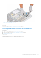
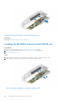
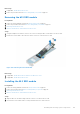

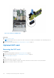
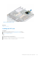
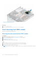

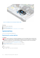
Table Of Contents
- Dell EMC PowerEdge R650xs Installation and Service Manual
- Contents
- About this document
- Dell EMC PowerEdge R650xs system overview
- Initial system setup and configuration
- Minimum to POST and system management configuration validation
- Installing and removing system components
- Safety instructions
- Before working inside your system
- After working inside your system
- Recommended tools
- Optional front bezel
- System cover
- Drive backplane cover
- Air shroud
- Cooling fans
- Intrusion switch module
- Drives
- Optional optical drive
- Drive backplane
- Cable routing
- System memory
- Processor and heat sink module
- Expansion cards and expansion card risers
- Drive cage
- Optional serial COM port
- MicroSD card
- Optional BOSS S1 card
- Optional IDSDM module
- Optional OCP card
- Front mounting front PERC module
- System battery
- Optional internal USB card
- VGA module
- Power supply unit
- Power interposer board
- System board
- Trusted Platform Module
- Control panel
- Jumpers and connectors
- System diagnostics and indicator codes
- Getting help
- Documentation resources

3. Using the Phillips #1 screwdriver, secure the M.2 SSD module on the M.2 BOSS card with the screw.
NOTE: The numbers on the image do not depict the exact steps. The numbers are for representation of sequence.
Figure 106. Installing the M.2 SSD module
Next steps
1. If applicable, Install the M.2 BOSS card into the M.2 BOSS riser.
2. If applicable, Install the M,2 BOSS riser.
3. Follow the procedure listed in the After working inside your system on page 26.
Optional IDSDM module
Removing the IDSDM module
Prerequisites
1. Follow the safety guidelines listed in the Safety instructions on page 25.
2. Follow the procedure listed in Before working inside your system on page 26.
3. Remove the air shroud.
4. If you are replacing the IDSDM card, remove the MicroSD cards.
NOTE:
Temporarily label each SD card with its corresponding slot number before removal. Reinstall the SD cards into
the corresponding slots.
Steps
Holding the pull tab, lift the IDSDM card out of the system.
104
Installing and removing system components