
Installation and Service Manual
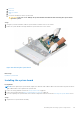
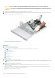
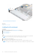
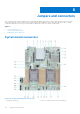
Table Of Contents
- Dell EMC PowerEdge R650xs Installation and Service Manual
- Contents
- About this document
- Dell EMC PowerEdge R650xs system overview
- Initial system setup and configuration
- Minimum to POST and system management configuration validation
- Installing and removing system components
- Safety instructions
- Before working inside your system
- After working inside your system
- Recommended tools
- Optional front bezel
- System cover
- Drive backplane cover
- Air shroud
- Cooling fans
- Intrusion switch module
- Drives
- Optional optical drive
- Drive backplane
- Cable routing
- System memory
- Processor and heat sink module
- Expansion cards and expansion card risers
- Drive cage
- Optional serial COM port
- MicroSD card
- Optional BOSS S1 card
- Optional IDSDM module
- Optional OCP card
- Front mounting front PERC module
- System battery
- Optional internal USB card
- VGA module
- Power supply unit
- Power interposer board
- System board
- Trusted Platform Module
- Control panel
- Jumpers and connectors
- System diagnostics and indicator codes
- Getting help
- Documentation resources

f. Processor
g. Heat sink
h. Memory modules
i. OCP
j. Disconnect all cables from the system board.
CAUTION: Take care not to damage the system identification button while removing the system board
from the system.
Steps
1. Using the system board holder, slide the system board toward the front of the chassis.
2. Incline the system board at an angle and lift the system board out of the chassis.
Figure 125. Removing the system board
Next steps
Install the system board.
Installing the system board
Prerequisites
NOTE:
Before replacing the system board, replace the old iDRAC MAC address label in the Information tag with the iDRAC
MAC address label of the replacement system board
1. Follow the safety guidelines listed in the Safety instructions on page 25.
2. Follow the procedure listed in Before working inside your system on page 26.
3. If you are replacing the system board, remove all the components that are listed in the removing the system board section.
Steps
1. Unpack the new system board assembly.
Installing and removing system components
121