
Installation and Service Manual
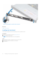
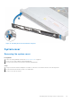
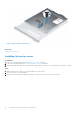
Table Of Contents
- Dell EMC PowerEdge R650xs Installation and Service Manual
- Contents
- About this document
- Dell EMC PowerEdge R650xs system overview
- Initial system setup and configuration
- Minimum to POST and system management configuration validation
- Installing and removing system components
- Safety instructions
- Before working inside your system
- After working inside your system
- Recommended tools
- Optional front bezel
- System cover
- Drive backplane cover
- Air shroud
- Cooling fans
- Intrusion switch module
- Drives
- Optional optical drive
- Drive backplane
- Cable routing
- System memory
- Processor and heat sink module
- Expansion cards and expansion card risers
- Drive cage
- Optional serial COM port
- MicroSD card
- Optional BOSS S1 card
- Optional IDSDM module
- Optional OCP card
- Front mounting front PERC module
- System battery
- Optional internal USB card
- VGA module
- Power supply unit
- Power interposer board
- System board
- Trusted Platform Module
- Control panel
- Jumpers and connectors
- System diagnostics and indicator codes
- Getting help
- Documentation resources

CAUTION: Many repairs may only be done by a certified service technician. You should only perform
troubleshooting and simple repairs as authorized in your product documentation, or as directed by the online or
telephone service and support team. Damage due to servicing that is not authorized by Dell is not covered by
your warranty. Read and follow the safety instructions that are shipped with your product.
NOTE: It is recommended that you always use an antistatic mat and antistatic strap while working on components inside
the system.
CAUTION: To ensure proper operation and cooling, all system bays and fans must always be populated with a
component or a blank.
NOTE: While replacing the hot swappable PSU, after next server boot; the new PSU automatically updates to the same
firmware and configuration of the replaced one. For more information about the Part replacement configuration, see the
Lifecycle Controller User's Guide at https://www.dell.com/idracmanuals.
NOTE: While replacing faulty storage controller, FC, or NIC card with the same type of card, after you power on the
system; the new card automatically updates to the same firmware and configuration of the faulty one. For more information
about the Part replacement configuration, see the Lifecycle Controller User's Guide at https://www.dell.com/idracmanuals.
Before working inside your system
Prerequisites
Follow the safety guidelines listed in the Safety instructions.
Steps
1. Power off the system and all attached peripherals.
2. Disconnect the system from the electrical outlet, and disconnect the peripherals.
3. If applicable, remove the system from the rack.
For more information, see the Rail Installation Guide relevant to your rail solutions at www.dell.com/poweredgemanuals.
4. Remove the system cover.
After working inside your system
Prerequisites
Follow the safety guidelines listed in Safety instructions.
Steps
1. Replace the system cover.
2. If applicable, install the system into the rack.
For more information, see the Rail Installation Guide relevant to your rail solutions at www.dell.com/poweredgemanuals.
3. Reconnect the peripherals and connect the system to the electrical outlet, and then power on the system.
Recommended tools
You need the following tools to perform the removal and installation procedures:
● Key to the bezel lock. The key is required only if your system includes a bezel.
● Phillips #1 screwdriver
● Phillips #2 screwdriver
● Torx #T30 screwdriver
● 5 mm hex nut screwdriver
● Plastic scribe
● 1/4-inch flat blade screwdriver
26
Installing and removing system components