
Installation and Service Manual
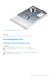
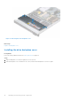
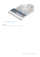
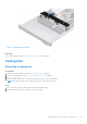
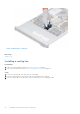
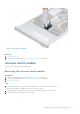
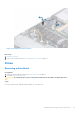
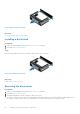
Table Of Contents
- Dell EMC PowerEdge R650xs Installation and Service Manual
- Contents
- About this document
- Dell EMC PowerEdge R650xs system overview
- Initial system setup and configuration
- Minimum to POST and system management configuration validation
- Installing and removing system components
- Safety instructions
- Before working inside your system
- After working inside your system
- Recommended tools
- Optional front bezel
- System cover
- Drive backplane cover
- Air shroud
- Cooling fans
- Intrusion switch module
- Drives
- Optional optical drive
- Drive backplane
- Cable routing
- System memory
- Processor and heat sink module
- Expansion cards and expansion card risers
- Drive cage
- Optional serial COM port
- MicroSD card
- Optional BOSS S1 card
- Optional IDSDM module
- Optional OCP card
- Front mounting front PERC module
- System battery
- Optional internal USB card
- VGA module
- Power supply unit
- Power interposer board
- System board
- Trusted Platform Module
- Control panel
- Jumpers and connectors
- System diagnostics and indicator codes
- Getting help
- Documentation resources

Figure 23. Installing the intrusion switch
Next steps
1. Install the air shroud.
2. Follow the procedure listed in After working inside your system on page 26.
Drives
Removing a drive blank
Prerequisites
1. Follow the safety guidelines listed in the Safety instructions on page 25.
2. If installed, remove the front bezel.
CAUTION: To maintain proper system cooling, drive blanks must be installed in all empty drive slots.
Steps
Press the release button, and slide the drive blank out of the drive slot.
Installing and removing system components
39