
Installation and Service Manual
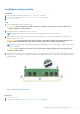
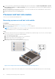
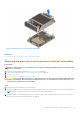
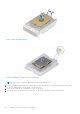
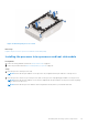
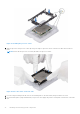
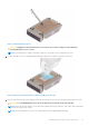
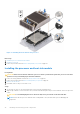
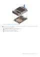
Table Of Contents
- Dell EMC PowerEdge R650xs Installation and Service Manual
- Contents
- About this document
- Dell EMC PowerEdge R650xs system overview
- Initial system setup and configuration
- Minimum to POST and system management configuration validation
- Installing and removing system components
- Safety instructions
- Before working inside your system
- After working inside your system
- Recommended tools
- Optional front bezel
- System cover
- Drive backplane cover
- Air shroud
- Cooling fans
- Intrusion switch module
- Drives
- Optional optical drive
- Drive backplane
- Cable routing
- System memory
- Processor and heat sink module
- Expansion cards and expansion card risers
- Drive cage
- Optional serial COM port
- MicroSD card
- Optional BOSS S1 card
- Optional IDSDM module
- Optional OCP card
- Front mounting front PERC module
- System battery
- Optional internal USB card
- VGA module
- Power supply unit
- Power interposer board
- System board
- Trusted Platform Module
- Control panel
- Jumpers and connectors
- System diagnostics and indicator codes
- Getting help
- Documentation resources

Installing a memory module
Prerequisites
1. Follow the safety guidelines listed in the Safety instructions on page 25.
2. Follow the procedure listed in Before working inside your system on page 26.
3. Remove the air shroud.
Steps
1. Locate the appropriate memory module socket.
CAUTION: Handle each memory module only by the card edges, ensuring not to touch the middle of the
memory module or metallic contacts.
2. If a memory module is installed in the socket, remove it.
NOTE: Ensure the socket ejector latches are fully open, before installing the memory module.
3. Align the edge connector of the memory module with the alignment key of the memory module socket, and insert the
memory module in the socket.
CAUTION: To prevent damage to the memory module or the memory module socket during installation, do
not bend or flex the memory module; insert both ends of the memory module simultaneously.
NOTE: The memory module socket has an alignment key that enables you to install the memory module in the socket in
only one orientation.
CAUTION: Do not apply pressure at the center of the memory module; apply pressure at both ends of the
memory module evenly.
4. Press the memory module with your thumbs until the ejectors firmly click into place. When the memory module is properly
seated in the socket, the levers on the memory module socket align with the levers on the other sockets that have memory
modules installed.
Figure 51. Installing a memory module
Next steps
1. Install the air shroud.
2. Follow the procedure listed in After working inside your system on page 26.
Installing and removing system components
61