
Installation and Service Manual
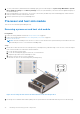
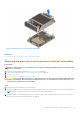
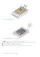
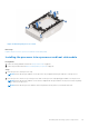
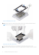
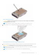
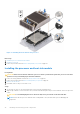
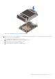
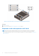
Table Of Contents
- Dell EMC PowerEdge R650xs Installation and Service Manual
- Contents
- About this document
- Dell EMC PowerEdge R650xs system overview
- Initial system setup and configuration
- Minimum to POST and system management configuration validation
- Installing and removing system components
- Safety instructions
- Before working inside your system
- After working inside your system
- Recommended tools
- Optional front bezel
- System cover
- Drive backplane cover
- Air shroud
- Cooling fans
- Intrusion switch module
- Drives
- Optional optical drive
- Drive backplane
- Cable routing
- System memory
- Processor and heat sink module
- Expansion cards and expansion card risers
- Drive cage
- Optional serial COM port
- MicroSD card
- Optional BOSS S1 card
- Optional IDSDM module
- Optional OCP card
- Front mounting front PERC module
- System battery
- Optional internal USB card
- VGA module
- Power supply unit
- Power interposer board
- System board
- Trusted Platform Module
- Control panel
- Jumpers and connectors
- System diagnostics and indicator codes
- Getting help
- Documentation resources

Figure 57. Installing the processor carrier
3. Align the processor with processor carrier by using your fingers to press the carrier on all the four sides until it clicks into
place.
NOTE: Ensure that the processor is securely latched to the processor carrier.
Figure 58. Press the carrier on the four sides
4. If you are using an existing heat sink, remove the thermal grease on the heat sink by using a clean lint-free cloth.
5. Use the thermal grease syringe included with your processor kit to apply the grease in a thin spiral on the bottom of the heat
sink.
66
Installing and removing system components