
Quick Start Guide
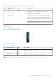
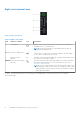
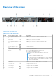
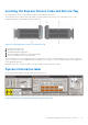
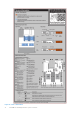
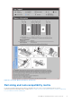
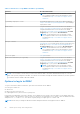
Table Of Contents
- Dell EMC PowerEdge R650xs Installation and Service Manual
- Contents
- About this document
- Dell EMC PowerEdge R650xs system overview
- Initial system setup and configuration
- Minimum to POST and system management configuration validation
- Installing and removing system components
- Safety instructions
- Before working inside your system
- After working inside your system
- Recommended tools
- Optional front bezel
- System cover
- Drive backplane cover
- Air shroud
- Cooling fans
- Intrusion switch module
- Drives
- Optional optical drive
- Drive backplane
- Cable routing
- System memory
- Processor and heat sink module
- Expansion cards and expansion card risers
- Drive cage
- Optional serial COM port
- MicroSD card
- Optional BOSS S1 card
- Optional IDSDM module
- Optional OCP card
- Front mounting front PERC module
- System battery
- Optional internal USB card
- VGA module
- Power supply unit
- Power interposer board
- System board
- Trusted Platform Module
- Control panel
- Jumpers and connectors
- System diagnostics and indicator codes
- Getting help
- Documentation resources

Table 3. Features available on the front of the system (continued)
Item Ports, panels, and
slots
Icon Description
2 VGA port Enables you to connect a display device to the system. For more
information, see the VGA port specifications section.
3 Right control panel N/A Contains the power button, USB port, iDRAC Direct micro port,
and the iDRAC Direct status LED.
4 Information tag
The Information tag is a slide-out label panel that contains
system information such as Service Tag, NIC, MAC address,
and so on. If you have opted for the secure default access
to iDRAC, the Information tag also contains the iDRAC secure
default password.
5 Drive N/A
Enables you to install drives that are supported on your system.
For more information about drives, see the Drives section.
For more information about the ports, see the Dell EMC PowerEdge R650xs Technical Specifications on the product
documentation page.
Left control panel view
Figure 4. Left control panel
Table 4. Left control panel
Item Indicator, button, or
connector
Icon Description
1 Status LED indicators NA
Indicates the status of the system. For more information, see the
Status LED indicators section.
2 System health and system
ID indicator
Indicates the status of the system. For more information, see the
System health and system ID indicator codes section.
NOTE: For more information about the indicator codes, see the System diagnostics and indicator codes section.
Dell EMC PowerEdge R650xs system overview 11