
Quick Start Guide
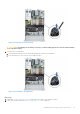
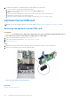

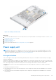
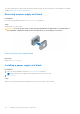
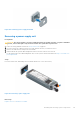
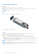

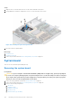
Table Of Contents
- Dell EMC PowerEdge R650xs Installation and Service Manual
- Contents
- About this document
- Dell EMC PowerEdge R650xs system overview
- Initial system setup and configuration
- Minimum to POST and system management configuration validation
- Installing and removing system components
- Safety instructions
- Before working inside your system
- After working inside your system
- Recommended tools
- Optional front bezel
- System cover
- Drive backplane cover
- Air shroud
- Cooling fans
- Intrusion switch module
- Drives
- Optional optical drive
- Drive backplane
- Cable routing
- System memory
- Processor and heat sink module
- Expansion cards and expansion card risers
- Drive cage
- Optional serial COM port
- MicroSD card
- Optional BOSS S1 card
- Optional IDSDM module
- Optional OCP card
- Front mounting front PERC module
- System battery
- Optional internal USB card
- VGA module
- Power supply unit
- Power interposer board
- System board
- Trusted Platform Module
- Control panel
- Jumpers and connectors
- System diagnostics and indicator codes
- Getting help
- Documentation resources

Figure 118. Installing the VGA module
Next steps
1. Route the VGA cable and connect it to the VGA connector on the system board. For locating the connector, see the System
board jumpers and connecters section.
2. Install the air shroud.
3. Install the backplane cover.
4. Install the front bezel.
5. Follow the procedure listed in After working inside your system on page 26.
.
Power supply unit
NOTE:
While replacing the hot swappable PSU, after next server boot; the new PSU automatically updates to the same
firmware and configuration of the replaced one. For more information about the Part replacement configuration, see the
Lifecycle Controller User's Guide at https://www.dell.com/idracmanuals
Hot spare feature
Your system supports the hot spare feature that significantly reduces the power overhead associated with the power supply
unit (PSU) redundancy.
When the hot spare feature is enabled, one of the redundant PSUs is switched to the sleep state. The active PSU supports 100
percent of the system load, thus operating at higher efficiency. The PSU in the sleep state monitors output voltage of the active
PSU. If the output voltage of the active PSU drops, the PSU in the sleep state returns to an active output state.
If having both PSUs active is more efficient than having one PSU in the sleep state, the active PSU can also activate the
sleeping PSU.
The default PSU settings are as follows:
● If the load on the active PSU is more than 50 percent of PSU rated power wattage, then the redundant PSU is switched to
the active state.
● If the load on the active PSU falls below 20 percent of PSU rated power wattage, then the redundant PSU is switched to
the sleep state.
Installing and removing system components
115