
Quick Start Guide
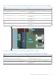
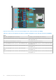
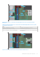
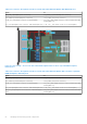
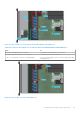
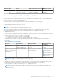
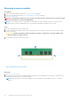
Table Of Contents
- Dell EMC PowerEdge R650xs Installation and Service Manual
- Contents
- About this document
- Dell EMC PowerEdge R650xs system overview
- Initial system setup and configuration
- Minimum to POST and system management configuration validation
- Installing and removing system components
- Safety instructions
- Before working inside your system
- After working inside your system
- Recommended tools
- Optional front bezel
- System cover
- Drive backplane cover
- Air shroud
- Cooling fans
- Intrusion switch module
- Drives
- Optional optical drive
- Drive backplane
- Cable routing
- System memory
- Processor and heat sink module
- Expansion cards and expansion card risers
- Drive cage
- Optional serial COM port
- MicroSD card
- Optional BOSS S1 card
- Optional IDSDM module
- Optional OCP card
- Front mounting front PERC module
- System battery
- Optional internal USB card
- VGA module
- Power supply unit
- Power interposer board
- System board
- Trusted Platform Module
- Control panel
- Jumpers and connectors
- System diagnostics and indicator codes
- Getting help
- Documentation resources

Table 16. Connector descriptions for 10 x 2.5-inch drive backplane to the onboard controller (6:4 NVMe)
From To
BP_PWR_1 (backplane power connector) SIG_PWR_1 (system board power connector)
DST_PA1 (backplane SATA connector, cable marking BP PA1) SL3_CPU1_PB2 (signal connector on the system board, cable
marking MB SL3)
SYS_PWR2 (system board power connector) CPU_PWR2 (PSU power connector)
DST_PB1 (backplane SATA connector, cable marking BP PB1) SL4_CPU1_PA2 (signal connector on the system board, cable
marking MB SL4)
DST_PA2 (backplane SATA connector, cable marking BP PA2) SL7_CPU1_PA4 (signal connector on the system board, cable
marking MB SL7)
DST_PB2 (backplane SATA connector, cable marking BP
PB2)
SL2_CPU2_PA1 (signal connector on the system board, cable
marking MB SL2)
DST_PA3 (backplane SATA connector, cable marking BP PA3) SL1_CPU2_PB1 (signal connector on the system board, cable
marking MB SL1)
Figure 39. Cable routing - 10 x 2.5-inch drive backplane with Butterfly riser and fPERC
Table 17. Connector descriptions for 10 x 2.5-inch drive backplane with Butterfly riser and fPERC
From To
BP_PWR_1 (backplane power connector) SIG_PWR_1 (system board power connector)
SYS_PWR2 (system board power connector) CPU_PWR2 (PSU power connector)
DST_PA3 (backplane SATA connector, cable marking BP PA3) CTRL_SRC_SB1 (fPERC connector on the backplane)
CTRL_DST_PA1 (fPERC connector on the backplane) SL3_CPU1_PB2 (signal connector on the system board, cable
marking MB SL3)
Installing and removing system components 51