
User Manual


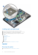


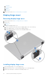
Table Of Contents
- Latitude 5490 Owner’s Manual
- Contents
- Working on your computer
- Removing and installing components
- Recommended tools
- Screw size list
- Subscriber Identity Module(SIM) board
- Base cover
- Battery
- Solid State Drive — optional
- Hard drive
- Coin-cell battery
- WLAN card
- WWAN card – optional
- Memory modules
- Keyboard lattice and Keyboard
- Heat sink
- System fan
- Power connector port
- Chassis frame
- SmartCard module
- Speaker
- System board
- Display hinge cover
- Display assembly
- Display bezel
- Display panel
- Display (eDP) cable
- Camera
- Display hinges
- Display back cover assembly
- Palm rest
- Technical specifications
- Technology and components
- System setup options
- BIOS overview
- Entering BIOS setup program
- Navigation keys
- One time boot menu
- Boot Sequence
- System Setup overview
- Accessing System Setup
- General screen options
- System Configuration screen options
- Video screen options
- Security screen options
- Secure Boot screen options
- Intel Software Guard Extensions
- Performance screen options
- Power Management screen options
- POST Behavior screen options
- Manageability
- Virtualization support screen options
- Wireless screen options
- Maintenance screen options
- Updating the BIOS
- System and setup password
- Clearing CMOS settings
- Clearing BIOS (System Setup) and System passwords
- Software
- Troubleshooting
- Contacting Dell

b. base cover
7. Follow the procedure in After working inside your computer.
Chassis frame
Removing the chassis frame
1. Follow the procedure in Before working inside your computer.
2. Remove the:
a. base cover
b. battery
c. hard drive
d. SSD card
e. SSD frame
f. WLAN card
g. WWAN card (optional)
NOTE: There are two different screw sizes for chassis frame: M2x5 8ea and M2x3 5ea
3. To release the chassis frame:
a. Unroute the WLAN cables from the routing channels [1].
b. Lift the latch and disconnect the keyboard backlight cable and the keyboard cable from their connectors [2,3,4,5] on the
system.
NOTE: There may be more than one cable to disconnect based on the keyboard type.
4. To remove the chassis frame:
Removing and installing components
31