
User Manual

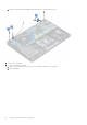


Table Of Contents
- Latitude 5490 Owner’s Manual
- Contents
- Working on your computer
- Removing and installing components
- Recommended tools
- Screw size list
- Subscriber Identity Module(SIM) board
- Base cover
- Battery
- Solid State Drive — optional
- Hard drive
- Coin-cell battery
- WLAN card
- WWAN card – optional
- Memory modules
- Keyboard lattice and Keyboard
- Heat sink
- System fan
- Power connector port
- Chassis frame
- SmartCard module
- Speaker
- System board
- Display hinge cover
- Display assembly
- Display bezel
- Display panel
- Display (eDP) cable
- Camera
- Display hinges
- Display back cover assembly
- Palm rest
- Technical specifications
- Technology and components
- System setup options
- BIOS overview
- Entering BIOS setup program
- Navigation keys
- One time boot menu
- Boot Sequence
- System Setup overview
- Accessing System Setup
- General screen options
- System Configuration screen options
- Video screen options
- Security screen options
- Secure Boot screen options
- Intel Software Guard Extensions
- Performance screen options
- Power Management screen options
- POST Behavior screen options
- Manageability
- Virtualization support screen options
- Wireless screen options
- Maintenance screen options
- Updating the BIOS
- System and setup password
- Clearing CMOS settings
- Clearing BIOS (System Setup) and System passwords
- Software
- Troubleshooting
- Contacting Dell

Installing display assembly
1. Place the chassis on a plane surface.
2. Align the display assembly with the screw holders on the system and place it on the chassis.
3. Close the display.
4. Replace the two screws that secure the display assembly.
5. Replace the screws that secure the power connector bracket and the display cable to the system.
6. Flip over the system and replace two screws to secure the display assembly to the system.
7. Replace the single screw that secure the power connector bracket and the display cable to the system.
8. Connect the display cables to the connectors on the system board.
9. Place the metal bracket to secure the display cable.
10. Replace the (M2x3) screws to secure the metal bracket to the system.
11. Route the WLAN and WWAN cables through the routing channels.
12. Install the:
a. hinge cover
b. WWAN card (optional)
c. WLAN card
d. battery
e. base cover
13. Follow the procedure in After working inside your computer.
Display bezel
Removing display bezel
1. Follow the procedure in Before working inside your computer.
2. Remove the:
a. base cover
b. battery
c. WLAN card
d. WWAN card (optional)
e. Display hinge cover
f. display assembly
3. To remove the display bezel:
a. Pry the display bezel at the base of the display [1].
NOTE:
When removing or reinstalling the display bezel from the display assembly, technicians should note that the
display bezel is secured to the LCD panel with a strong adhesive and care must be taken to avoid damage to LCD.
b. Lift the display bezel to release it [2].
c. Pry the edges on the side of the display to release the display bezel [3, 4,,5].
CAUTION:
The adhesive used on the LCD bezel to seal it with the LCD itself, makes it hard to remove the
bezel as the adhesive is very strong and tends to stay stuck to the LCD portion and can peel the layers up
or crack the glass when trying to pry the two items apart.
44 Removing and installing components