Dell Force10 S25 Systems Quick Start Guide Regulatory Model: S25N/S25V/S25P
Dell Force10 S25 Systems Quick Start Guide Regulatory Model: S25N/S25V/S25P
Notes, Cautions, and Warnings NOTE: A NOTE indicates important information that helps you make better use of your computer. CAUTION: A CAUTION indicates potential damage to hardware or loss of data if instructions are not followed. WARNING: A WARNING indicates a potential for property damage, personal injury, or death. If you purchased a Dell n Series computer, any references in this publication to Microsoft Windows operating systems are not applicable.
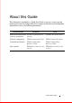
About this Guide This document is intended as a Quick Start Guide to get new systems up and running and ready for configuration.
4 About this Guide
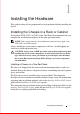
1 Installing the Hardware This guide assumes all site preparation has been performed before installing the chassis. Installing the Chassis in a Rack or Cabinet To install the S25N, S25V, or S25P system, Dell Force10 recommends that you complete the installation procedures in the order presented below. NOTE: Unless stated otherwise, the installation instructions below apply to the S25N, S25V, and S25P systems. Always handle the system and its components with care.
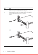
Step Task 1 Dell Force10 recommends that one person hold the chassis in place while a second person attaches the brackets to the posts. 2 Position the unit in the rack. Secure the unit with two of the supplied screws through each bracket and onto the rack post.
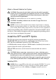
Attach a Ground Cable to the System CAUTION: To prevent electrical shock, make sure the switch is grounded properly. If you do not ground your equipment correctly, excessive emissions can result. Use a qualified electrician to ensure that the power cables meet your local electrical requirements. NOTE: The rack installation ears are not suitable for grounding. CAUTION: Grounding conductors must be made of copper. Do not use aluminum conductors.
CAUTION: Electrostatic discharge (ESD) damage can occur if components are mishandled. Always wear an ESD-preventive wrist or heel ground strap when handling the chassis and its components. WARNING: Follow all warning labels when working with optical fibers. Always wear eye protection when working with optical fibers. Never look directly into the end of a terminated or unterminated fiber or connector as it may cause eye damage. Step Task 1 Position the SFP so it is in the upright position.
Installing XFPs CAUTION: Electrostatic discharge (ESD) damage can occur if components are mishandled. Always wear an ESD-preventive wrist or heel ground strap when handling the chassis and its components. WARNING: Follow all warning labels when working with optical fibers. Always wear eye protection when working with optical fibers. Never look directly into the end of a terminated or unterminated fiber or connector as it may cause eye damage.
Power Up Sequence Supply Power and Power Up the System There is no power switch. Supply power to the unit only after it is mounted. CAUTION: To prevent electrical shock, make sure the switch is grounded properly. If you do not ground your equipment correctly, excessive emissions can result. Use a qualified electrician to ensure that the power cables meet your local electrical requirements. NOTE: A US AC power cable is included in the shipping container for powering up an AC power supply.
Step Task 3 Connect the -48 V and -48 V RTN (Return) cables to the switch terminals and then to the remote power sources. 4 Replace the safety covers on the DC terminal block. S25P The S25P has two AC power supplies acting in load-sharing mode or can be used independently. Use the power cords shipped with the S25P to connect it to AC power outlets, ideally on separate circuits. Several versions of the power cord are available, based on country requirements.
CAUTION: Electrostatic discharge (ESD) damage can occur if components are mishandled. Always wear an ESD-preventive wrist or heel ground strap when handling the system and its components. Power Supplies On the S25N, S25V, and S25P systems, either the AC or DC power supplies alone are sufficient to power the switch. When both AC and DC power supplies are connected, they act in roughly a 60%/40% load-sharing mode. WARNING: To prevent electrical shock, make sure the system is grounded properly.
Specifications Chassis Physical Design Parameter S25N/V Specifications S25P Specifications Height 1.73 inches (4.4 cm) 1.73 inches (4.4 cm) Width 17.32 inches (44.0 cm) (19" rack-mountable) 17.32 inches (44.0 cm) (19" rack-mountable) Depth 16.73 inches (42.5cm) (standard 1 rack unit) 16.73 inches (42.5cm) (standard 1 rack unit) Chassis weight with factory-installed components 19.5 pounds (approx.) (8.85 kg) 14.41 pounds (approx.) (6.54 kg) Rack clearance required Front: 5-inches (12.
Parameter S25N/V Specifications S25P Specifications ISO 7779 A-weighted sound pressure level S25N: 42.0 dBA at 73.4°F (23°C) 45.1 dBA at 73.4°F (23°C) S25V: 42.9 dBA at 73.4°F (23°C) Power Requirements Parameter S25N/V Specifications S25P Specifications Nominal Input Voltage 90 – 254 VAC, 47/63 Hz S25P: 90 – 254 VAC, 47/63 Hz S25P-DC: -48 VDC Maximum Current Draw S25N: 2 A @ 100/120 VAC; 1 S25P: 2 A @ 100/120 VAC; 1 A @ 200/240 VAC A @ 200/240 VAC S25V (AC): 6.5 A @ 100/120 S25P-DC: 3.
2 Installing the Software Navigating CLI Modes The FTOS prompt changes to indicate the CLI mode. You must move linearly through the command modes, with the exception of the end command which takes you directly to EXEC Privilege mode; the exit command moves you up one command mode level. Console Access Access the command line through a serial console port or a Telnet session. When the system successfully boots, you enter the command line in the EXEC mode.
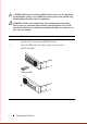
Sta ck ID AC 1 P2 5 P2 6 XF XF Ala rm AC 2 27 P2 8 Step 1 Task Install the RJ-45 copper cable that is shipped with the system into the console port. CAUTION: You must install a straight-through RJ-45 copper cable (a standard Ethernet cable) into the console port. This is different from many other implementations that require an Ethernet crossover cable (or rollover cable).
Step 3 Task Set your initial console terminal settings to match the default console settings on the switch. 9600 baud rate No parity 8 data bits 1 stop bit No flow control (console port only) After establishing a connection, you can modify the settings to match at each end of the connection. 4 S25P only: If you use the console port to download software to the switch, you will probably want to raise the console baud rate. Establish a connection with the default settings to verify the connection.
Default Configuration A version of the Dell Force10 Operating System (FTOS) is pre-loaded onto the chassis, however the system is not configured when you power up for the first time (except for the default hostname, which is Force10). You must configure the system using the Command Line Interface (CLI). Configure Layer 2 (Data Link) Mode Use the switchport command in INTERFACE mode to enable Layer 2 data transmissions through an individual interface.
The S25N, S25V, and S25P systems do not have a dedicated management port, nor a separate management routing able. Configure any port on one of the chassis to be the port through which you manage the system and configure an IP route to that gateway. Step Task Command Syntax Command Mode 1 Configure an IP address for the port through which you will manage the system. ip address INTERFACE 2 Configure an IP route with a default gateway. ip route CONFIGURATION 3 Configure a username and password.
Task Command Syntax Configure a management route ip-address/mask management route to gateway the network from which you are accessing the system. Command Mode CONFIGURATION Configure a Username and Password In FTOS, you can assign a specific username to limit user access to the system. Task Command Syntax Command Mode Configure a username and password to access the system remotely.
Create a VLAN The Default VLAN is part of the system startup configuration, and is by default, VLAN 1. You may make another VLAN the Default VLAN. The Default VLAN cannot be deleted, disabled, or configured (you cannot assign it an IP address), and only untagged interfaces can belong to it. When an interface is configured, a switchport automatically places it in the default VLAN as an untagged interface.
Step Task Command Syntax Command Mode 1 Assign a switchport to [tagged | untagged] interface a VLAN. INTERFACE VLAN 2 Display all show vlan switchports and the VLANs of which they are members. EXEC Privilege Assign an IP address to a VLAN NOTE: An IP address cannot be assigned to the Default VLAN, which, by default, is VLAN 1. To assign another VLAN ID to the Default VLAN, use the default vlan-id vlan-id command.
Printed in the U.S.A. w w w. d e l l . c om | s u p p o r t . d e l l .