
Installation Guide

4. Disassembly and Assembly Procedures
4.1 Disassembly Procedures:
Necessary repair and test equipment:
1. Philips-head screwdriver
S3
S2
S1
S1
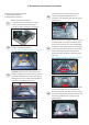
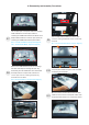
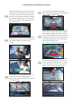
Remove the monitor stand base:
1. Place the monitor on a soft cloth or cushion.
2. Press and hold the stand-release button.
3. Lift the stand up and away from the monitor.
S6
S4
S5
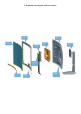
Wedge your fingers between the rear cover and the
middle bezel on the corners of the top side of the
monitor to release the rear cover, then use one hand
to press the middle bezel, the other hand to pull up
carefully the rear cover in order of arrow preference
for unlocking mechanisms of rear cover.
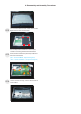
Use a Philips-head screwdriver to remove four
screws for unlocking mechanisms.
(No.1~4 screw size=M4x8; Torque=10~11kgfxcm)
2
3
4
1
4
3
2
3
1
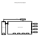
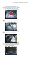
Lift the rear cover up carefully. Disconnect the
function key cable and LED cable from the
connectors of the interface board, and then remove
the rear cover.
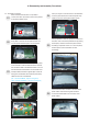
Put the rear cover on a protective cushion. Tear off
the shading tape, then release the diffusion sheet
from the hook of the rear cover. Use a Philips-head
screwdriver to remove 4pcs screws for unlocking the
function key board with the rear cover. Tear off 2pcs
tapes for releasing the function key cable, then
release the function key board from the hook of the
rear cover.
(No.1~4 screw size=M2x0.2, Torque=0.8±0.2kgfxcm)
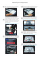
Tear off 1pcs aluminum foil for uncovering the LVDS
connector and cables, then tear off the tapes to
disconnect the panel cable away from the connector
of the panel module. Disconnect the power key cable
and touch key cable from the connectors of the
interface board.
1
3
4
2