
Release Notes


5 Balanced Memory with 2
nd
Generation AMD EPYC
TM
Processors for PowerEdge Servers
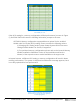
2. Memory Topography and Terminology
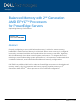
Figure 1: CPU-to-memory subsystem connectivity for Rome processors
To understand the relationship between the CPU and memory, terminology illustrated in
Figure 1 must first be defined:
• Memory controllers are digital circuits that manage the flow of data going from the
computer’s main memory to the corresponding memory channels.
2
Rome
processors have eight memory controllers in the processor I/O die, with one
controller assigned to each channel.
• Memory channels are the physical layer on which the data travels between the
CPU and memory modules.
3
As seen in Figure 1, Rome processors have eight
memory channels designated A, B, C, D, E, F, G and H. These channels were
intended to be organized into pairs such as two-way (AB, CD, EF, GH), four-way
(ABCD, EFGH) or eight-way (ABCDEFGH).
• The memory slots are internal ports that connect the individual DIMMs to their
respective channels.
4
Rome processors have two slots per channel, so there are a
total of sixteen slots per CPU for memory module population. DIMM 1 slots are the
first eight memory modules to be populated while DIMM 0 slots are the last eight.
In the illustrations ahead, DIMM 1 slots will be represented with black text marked
A1-A8 and DIMM 0 slots will be represented with white text marked A9-A16.
• The memory subsystem is the combination of all the independent memory functions
listed above.