VXLAN and BGP EVPN Configuration Guide for Dell EMC SmartFabric OS10 Release 10.5.1 Feb 2021 Rev.
Notes, cautions, and warnings NOTE: A NOTE indicates important information that helps you make better use of your product. CAUTION: A CAUTION indicates either potential damage to hardware or loss of data and tells you how to avoid the problem. WARNING: A WARNING indicates a potential for property damage, personal injury, or death.
Contents Chapter 1: VXLAN .........................................................................................................................6 VXLAN concepts..................................................................................................................................................................7 VXLAN as NVO solution.....................................................................................................................................................
show mac address-table nve.................................................................................................................................... 34 show mac address-table virtual-network.............................................................................................................. 34 Example: VXLAN with static VTEP...............................................................................................................................35 Chapter 2: BGP EVPN for VXLAN........
Assign interfaces to be managed by the controller...........................................................................................166 Service Nodes.............................................................................................................................................................166 View replicators..........................................................................................................................................................
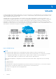
1 VXLAN A virtual extensible LAN (VXLAN) extends Layer 2 (L2) server connectivity over an underlying Layer 3 (L3) transport network in a virtualized data center. A virtualized data center consists of virtual machines (VMs) in a multi-tenant environment. OS10 supports VXLAN as described in RFC 7348. VXLAN provides a L2 overlay mechanism on an existing L3 network by encapsulating the L2 frames in L3 packets.
Topics: • • • • • • • • • • VXLAN concepts VXLAN as NVO solution Configure VXLAN L3 VXLAN route scaling DHCP relay on VTEPs View VXLAN configuration VXLAN MAC addresses VXLAN commands VXLAN MAC commands Example: VXLAN with static VTEP VXLAN concepts Network virtualization overlay (NVO) An overlay network extends L2 connectivity between server virtual machines (VMs) in a tenant segment over an underlay L3 IP network.
Port-scoped VLAN A Port,VLAN pair that maps to a virtual network ID (VNID) in OS10. Assign an individual member interface to a virtual network either with an associated tagged VLAN or as an untagged member. Using a portscoped VLAN, you can configure: ● The same VLAN ID on different access interfaces to different virtual networks. ● Different VLAN IDs on different access interfaces to the same virtual network.
4. Enter NVE mode from CONFIGURATION mode. NVE mode allows you to configure the VXLAN tunnel endpoint on the switch. nve 5. Configure the Loopback interface as the source tunnel endpoint for all virtual networks on the switch in NVE mode. source-interface loopback number 6. Return to CONFIGURATION mode. exit Configure a VXLAN virtual network To create a VXLAN, assign a VXLAN segment ID (VNI) to a virtual network ID (VNID) and configure a remote VTEP. A unique 2-byte VNID identifies a virtual network.
switchport trunk allowed-vlan vlan-id exit The local physical ports assigned to the VLAN transmit packets over the virtual network. NOTE: A switch-scoped VLAN assigned to a virtual network cannot have a configured IP address and cannot participate in L3 routing; for example: OS10(config)# interface vlan 102 OS10(conf-if-vlan-102)# ip address 1.1.1.1/24 % Error: vlan102, IP address cannot be configured for VLAN attached to Virtual Network.
2. Configure port interfaces as trunk members and remove the access VLAN in Interface mode. interface ethernet node/slot/port[:subport] switchport mode trunk no switchport access vlan exit 3. Assign the trunk interfaces as untagged members of the virtual network in VIRTUAL-NETWORK mode. You cannot use the reserved VLAN ID for a legacy VLAN or for tagged traffic on member interfaces of virtual networks.
no shutdown exit 4. Configure an anycast gateway IPv4 or IPv6 address for each virtual network in INTERFACE-VIRTUAL-NETWORK mode. This anycast IP address must be in the same subnet as the IP address of the virtual-network interface in Step 3. Configure the same IPv4 or IPv6 address as the anycast IP address on all VTEPs in a virtual network. All hosts use the anycast gateway IP address as the default gateway IP address in the subnet that connects to the virtual-network interface configured in Step 3.
Table 1. MAC address for all VTEPs (continued) Virtual network VTEP Anycast gateway MAC address VTEP 3 00.11.22.33.44.55 ● Configure a unique IP address on the virtual-network interface on each VTEP across all virtual networks. Configure the same anycast gateway IP address on all VTEPs in a virtual-network subnet. For example: Table 2. IP address on the virtual-network interface on each VTEP Virtual network VTEP Virtual-network IP address Anycast gateway IP address VNID 11 VTEP 1 10.10.1.
● If you use a port-scoped VLAN to assign tagged access interfaces to a virtual network, to identify traffic belonging to each virtual network, you must configure a unique VLAN ID for the VLT Interconnect (VLTi) link. ● Configure a VLAN to transmit VXLAN traffic over the VLTi link in VIRTUAL-NETWORK mode. All traffic sent and received from a virtual network on the VLTi carries the VLTi VLAN ID tag. Configure the same VLTi VLAN ID on both VLT peers.
Table 3.
which the underlay and overlay are in different VRFs, the default DHCP method is not successful. The IP tenant subnet is in the overlay address space. The IP address where the VTEP is reachable is in the underlay address space. To transmit the IP subnet of the client separately from the IP address where the VTEP is reachable, you must configure an additional DHCP sub-option (5 or 151) in DHCP relay agent option 82.
@ – Attached to Virtual Network Q: A - Access (Untagged), T - Tagged NUM * 1 @ 100 @ 101 200 Status Description Q Ports up A Eth1/1/1-1/1/48 up T Eth1/1/2,Eth1/1/3 A Eth1/1/1 up T port-channel5 up T Eth1/1/11-1/1/15 View the VXLAN virtual-network statistics OS10# show virtual-network counters Virtual-Network Input (Packets/Bytes) 1000 857/8570 2000 457/3570 Output (Packets/Bytes) 257/23709 277/13709 OS10# show virtual-network counters interface 1/1/3 vlan 100 Virtual-Network Input (Packets/Bytes) Output
121.0.0.4 00:f2:34:ac:34:09 virtual-network20 VXLAN(20.0.0.1) OS10# show ipv6 neighbors vrf tenant1 IPv6 Address Hardware Address State Interface Egress Interface ---------------------------------------------------------------------------200::2 00:12:28:1f:34:15 STALE virtual-network40 port-channel5 200::f 00:f2:34:ac:34:09 REACH virtual-network40 VXLAN(20.0.0.
Table 4. Display VXLAN MAC addresses (continued) Command Description dynamic: Displays only dynamic MAC addresses. address mac-address: Displays only information about the specified MAC address. interface ethernet node/slot/port:subport: Displays only MAC addresses learned on the specified interface. interface port-channel number: Displays only MAC addresses learned on the specified port channel.
Table 4. Display VXLAN MAC addresses (continued) Command Description vxlan-vni vn-id: Displays the number of MAC addresses learned on the specified VXLAN virtual network. show mac address-table count extended [interface ethernet node/slot/port:subport | port-channel number]} Displays the number of MAC addresses learned on all VLANs and VXLAN virtual networks. interface ethernet node/slot/port:subport: Displays the number of MAC addresses learned from VLANs and VXLANs on the specified interface.
disableoverlayrouting Default Allocate 0 next-hop entries for overlay routing and all next-hop entries for underlay routing. S4048T-ON and S6010-ON switches reserve 8192 ARP table entries. S4100-ON series switches reserve 4096 ARP table entries. S5200-ON series switches reserve 8192 ARP table entries. Command mode CONFIGURATION Usage information The number of reserved table entries in a profile varies according to the OS10 switch.
Usage information Example Supported releases Configure the same anycast gateway IP address on all VTEPs in a VXLAN virtual network. Use the anycast gateway IP address as the default gateway IP address if the host VMs move from one VTEP to another in a VXLAN. The anycast gateway IP address must be in the same subnet as the IP address of the virtual-network router interface. OS10(config)# interface virtual-network 10000 OS10(config-if-vn-10000)# ip virtual-router address 10.1.0.100 10.4.3.
Example Supported releases OS10(config)# virtual-network 10000 OS10(config-vn)# member-interface port-channel 10 vlan-tag 200 OS10(config-vn)# member-interface port-channel 20 untagged 10.4.2.0 or later nve Enters network virtualization edge (NVE) configuration mode to configure the source VXLAN tunnel endpoint. Syntax nve Parameters None Default None Command mode CONFIGURATION Usage information In NVE mode, configure the source tunnel endpoint for all virtual networks on the switch.
Command mode EXEC Usage information On S4100-ON series, S5200-ON series, S4048T-ON, S4248-ON, and S6010-ON switches, L3 VXLAN overlay routing requires reserved hardware resources. The number of reserved table entries in a profile varies according to the OS10 switch.
show nve remote-vtep Displays information about remote VXLAN tunnel endpoints. Syntax Parameters show nve remote-vtep [ip-address | summary | counters] ip-address Display detailed information about a specified remote VTEP. summary Display summary information about remote VTEPs. counters Display statistics on remote VTEP traffic. Default Not configured Command mode EXEC Usage information Use this command to display the IP address, operational state, and configured VXLANs for each remote VTEP.
Parameters None Default Not configured Command mode EXEC Usage information Use this command to display information about configured VXLAN virtual networks. Each VXLAN virtual network is identified by its virtual-network ID. Example Supported releases OS10# show nve vxlan-vni VNI Virtual-Network Source-IP Remote-VTEPs -----------------------------------------------------10000 1 1.1.1.1 2.2.2.2 200 2 1.1.1.1 2.2.2.2 300 300 1.1.1.1 2.2.2.2 10.4.2.
Example Supported releases OS10# show virtual-network counters Virtual-Network Input (Packets/Bytes) 1000 857/8570 2000 457/3570 Output (Packets/Bytes) 257/23709 277/13709 10.4.2.0 or later show virtual-network interface counters Displays packet statistics for a member port, port channel, or VLAN in VXLAN virtual networks.
Command mode EXEC Usage information Use this command to verify the VXLAN VLANs where an Ethernet port connected to downstream servers is a member. Example Supported releases OS10# show virtual-network interface ethernet 1/1/1 Interface Vlan Virtual-network ethernet1/1/1 100 1000 ethernet1/1/1 200 2000 ethernet1/1/1 300 3000 10.4.2.0 or later show virtual-network vlan Displays the VXLAN virtual networks where a VLAN is assigned.
Supported releases 10.4.2.0 or later source-interface loopback Configures a dedicated Loopback interface as the source VTEP. Syntax Parameters source-interface loopback number loopback number Enter the Loopback interface used as the source interface of a VXLAN virtual tunnel, from 0 to 16383. Default Not configured Command mode NVE-INSTANCE Usage information The IP address of the Loopback interface serves as the source IP address in encapsulated packets transmitted from the switch as an NVE VTEP.
Default Not configured Command mode CONFIGURATION Usage information The untagged VLAN ID is used internally for all untagged member interfaces that belong to virtual networks. You cannot use the reserved untagged VLAN ID for a simple VLAN bridge or for tagged traffic on member interfaces of virtual networks. The no version of this command removes the configured value. Example Supported releases OS10(config)# virtual-network untagged-vlan 10 10.4.2.
clear mac address-table dynamic virtual-network Clears MAC addresses learned on all or a specified VXLAN virtual network. Syntax Parameters clear mac address-table dynamic virtual-network [interface {ethernet node/ slot/port:subport | port-channel number} | local | vn-id [address macaddress | local]] interface ethernet node/slot/ port[:subport ] Clear all MAC addresses learned on the specified interface. interface port-channel number Clear all MAC addresses learned on the specified port channel.
Usage information Example Supported releases Use this command to display the number of MAC address entries learned on all VLANs and VXLAN virtual networks. OS10# show mac address-table count extended MAC Entries for all vlans : Dynamic Address Count : 10 Static Address (User-defined) Count : 2 Total MAC Addresses in Use: 12 10.4.2.0 or later show mac address-table count nve Displays the number of MAC addresses learned on a VXLAN virtual network or from a remote VXLAN tunnel endpoint.
interface ethernet node/slot/ port[:subport ] Display the number of MAC addresses learned on the specified interface. interface port-channel number Display the number of MAC addresses learned on the specified port channel. vn-id Display the number of MAC addresses learned on the specified virtual network, from 1 to 65535. Default Not configured Command mode EXEC Usage information Use this command to display the number of MAC address entries learned on virtual networks in the MAC address table.
10000 10000 10000 10000 20000 20000 20000 20000 Supported releases 1 500 4000 100 100 300 300 300 aa:bb:cc:dd:f0:03 aa:bb:cc:dd:f0:03 aa:bb:cc:dd:f0:03 00:00:00:00:00:11 00:00:00:00:00:44 00:00:00:00:00:55 00:00:00:00:00:77 00:00:00:00:00:22 00:00:00:00:00:33 00:00:00:00:00:66 00:00:00:00:00:88 static static static dynamic dynamic dynamic dynamic dynamic dynamic dynamic dynamic port-channel1000 port-channel1000 port-channel1000 ethernet1/1/31:1 port-channel1000 port-channel10 VxLAN(32.1.1.
dynamic Display only dynamic MAC addresses. address macaddress Display only information about the specified MAC address. Enter the MAC address in EEEE.EEEE.EEEE format. interface ethernet node/slot/ port[:subport ] Display only MAC addresses learned on the specified interface. interface port-channel number Display only MAC addresses learned on the specified port channel.
Figure 2. Static VXLAN use case VTEP 1 Leaf Switch 1. Configure the underlay OSPF protocol Do not configure the same IP address for the router ID and the source loopback interface in Step 2. OS10(config)# router ospf 1 OS10(config-router-ospf-1)# router-id 172.16.0.1 OS10(config-router-ospf-1)# exit 2. Configure a Loopback interface OS10(config)# interface loopback0 OS10(conf-if-lo-0)# no shutdown OS10(conf-if-lo-0)# ip address 192.168.1.1/32 OS10(conf-if-lo-0)# ip ospf 1 area 0.0.0.
3. Configure the Loopback interface as the VXLAN source tunnel interface OS10(config)# nve OS10(config-nve)# source-interface loopback0 OS10(config-nve)# exit 4.
OS10(conf-if-eth1/1/2)# OS10(conf-if-eth1/1/1)# OS10(conf-if-eth1/1/2)# OS10(conf-if-eth1/1/2)# OS10(conf-if-eth1/1/2)# no switchport mtu 1650 ip address 172.16.2.0/31 ip ospf 1 area 0.0.0.0 exit 8. Configure VLT Configure a dedicated L3 underlay path to reach the VLT Peer in case of network failure OS10(config)# interface vlan4000 OS10(config-if-vl-4000)# no shutdown OS10(config-if-vl-4000)# ip address 172.16.250.1/30 OS10(config-if-vl-4000)# ip ospf 1 area 0.0.0.
OS10(config-if-vn-10000)# ip address 10.1.0.231/16 OS10(config-if-vn-10000)# ip virtual-router address 10.1.0.100 OS10(config-if-vn-10000)# no shutdown OS10(config-if-vn-10000)# exit OS10(config)# interface virtual-network 20000 OS10(config-if-vn-20000)# ip vrf forwarding tenant1 OS10(config-if-vn-20000)# ip address 10.2.0.231/16 OS10(config-if-vn-20000)# ip virtual-router address 10.2.0.100 OS10(config-if-vn-20000)# no shutdown OS10(config-if-vn-20000)# exit VTEP 2 Leaf Switch 1.
OS10(conf-if-po-10)# switchport access vlan 200 OS10(conf-if-po-10)# exit OS10(config)# interface OS10(conf-if-eth1/1/5)# OS10(conf-if-eth1/1/5)# OS10(conf-if-eth1/1/5)# OS10(conf-if-eth1/1/5)# ethernet1/1/5 no shutdown channel-group 10 mode active no switchport exit OS10(config)# interface port-channel20 OS10(conf-if-po-20)# no shutdown OS10(conf-if-po-20)# switchport mode access OS10(conf-if-po-20)# switchport access vlan 200 OS10(conf-if-po-20)# exit OS10(config)# interface OS10(conf-if-eth1/1/6)# OS10
Configure a VLT domain OS10(config)# vlt-domain 1 OS10(conf-vlt-1)# backup destination 10.16.150.
4. Configure VXLAN virtual networks with a static VTEP OS10(config)# virtual-network 10000 OS10(config-vn-10000)# vxlan-vni 10000 OS10(config-vn-vxlan-vni)# remote-vtep OS10(config-vn-vxlan-vni-remote-vtep)# OS10(config-vn-vxlan-vni)# exit OS10(config-vn-10000)# exit OS10(config)# virtual-network 20000 OS10(config-vn-20000)# vxlan-vni 20000 OS10(config-vn-vxlan-vni)# remote-vtep OS10(config-vn-vxlan-vni-remote-vtep)# OS10(config-vn-vxlan-vni)# exit OS10(config-vn-20000)# exit 192.168.1.1 exit 192.168.1.
OS10(conf-if-eth1/1/2)# OS10(conf-if-eth1/1/1)# OS10(conf-if-eth1/1/2)# OS10(conf-if-eth1/1/2)# OS10(conf-if-eth1/1/2)# no switchport mtu 1650 ip address 172.18.2.0/31 ip ospf 1 area 0.0.0.0 exit 9.
Configure an anycast L3 gateway OS10(config)# ip virtual-router mac-address 00:01:01:01:01:01 Configure routing with an anycast gateway IP address for each virtual network OS10(config)# interface virtual-network 10000 OS10(config-if-vn-10000)# ip vrf forwarding tenant1 OS10(config-if-vn-10000)# ip address 10.1.0.233/16 OS10(config-if-vn-10000)# ip virtual-router address 10.1.0.
OS10(conf-if-po-10)# no switchport access vlan OS10(conf-if-po-10)# exit OS10(config)# interface OS10(conf-if-eth1/1/5)# OS10(conf-if-eth1/1/5)# OS10(conf-if-eth1/1/5)# OS10(conf-if-eth1/1/5)# ethernet1/1/5 no shutdown channel-group 10 mode active no switchport exit OS10(config)# interface port-channel20 OS10(conf-if-po-20)# no shutdown OS10(conf-if-po-20)# switchport mode trunk OS10(conf-if-po-20)# no switchport access vlan OS10(conf-if-po-20)# exit OS10(config)# interface OS10(conf-if-eth1/1/6)# OS10(co
OS10(conf-if-po-10)# exit OS10(config)# interface port-channel20 OS10(conf-if-po-20)# vlt port-channel 20 OS10(conf-if-po-20)# exit Configure VLTi member links OS10(config)# interface OS10(conf-if-eth1/1/3)# OS10(conf-if-eth1/1/3)# OS10(conf-if-eth1/1/3)# ethernet1/1/3 no shutdown no switchport exit OS10(config)# interface OS10(conf-if-eth1/1/4)# OS10(conf-if-eth1/1/4)# OS10(conf-if-eth1/1/4)# ethernet1/1/4 no shutdown no switchport exit Configure a VLT domain OS10(config)# vlt-domain 1 OS10(conf-vlt-1)
OS10(conf-if-eth1/1/1)# OS10(conf-if-eth1/1/1)# OS10(conf-if-eth1/1/1)# OS10(conf-if-eth1/1/1)# no switchport ip address 172.16.1.1/31 ip ospf 1 area 0.0.0.0 exit OS10(config)# interface OS10(conf-if-eth1/1/2)# OS10(conf-if-eth1/1/2)# OS10(conf-if-eth1/1/2)# OS10(conf-if-eth1/1/2)# OS10(conf-if-eth1/1/2)# ethernet1/1/2 no shutdown no switchport ip address 172.17.1.1/31 ip ospf 1 area 0.0.0.
2 BGP EVPN for VXLAN Ethernet Virtual Private Network (EVPN) is a control plane for VXLAN that reduces flooding in the network and resolves scalability concerns. EVPN uses MP-BGP to exchange information between VTEPs. EVPN was introduced in RFC 7432 and is based on BGP MPLS-based VPNs. RFC 8365 describes VXLAN-based EVPN. The MP-BGP EVPN control plane provides protocol-based remote VTEP discovery, and MAC and ARP learning. This configuration reduces flooding related to L2 unknown unicast traffic.
Table 6. Differences between Static VXLAN and VXLAN BGP EVPN Static VXLAN VXLAN BGP EVPN To start sending and receiving virtual-network traffic to and from a remote VTEP, manually configure the VTEP as a member of the virtual network. No manual configuration is required. Each remote VTEP is automatically learned as a member of a virtual network from the EVPN routes received from the remote VTEP. After a remote VTEP address is learned, VXLAN traffic is sent to, and received from, the VTEP.
Leaf nodes are typically top-of-rack (ToR) switches in a data center network. They act as the VXLAN tunnel endpoints and perform VXLAN encapsulation and decapsulation. Leaf nodes also participate in the MP-BGP EVPN to support control plane and data plane functions. Control plane functions include: ● Initiate and maintain route adjacencies using any routing protocol in the underlay network. ● Advertise locally learned routes to all MP-BGP EVPN peers.
the export RT associated with the EVI. A receiving VTEP downloads information in the BGP EVPN route to EVIs that have a matching import RT value. You can autogenerate or manually configure the RT import and export for each EVI. In auto-EVI mode, RT autogenerates. In manual EVI configuration mode, you can autogenerate or manually configure the RT. The RT consists of a 2-octet type and a 6-octet value.
g. Assign the BGP neighbor to an autonomous system in ROUTER-BGP-NEIGHBOR mode. remote-as as-number h. Enable the peer session with the BGP neighbor in ROUTER-BGP-NEIGHBOR mode. no shutdown i. Return to ROUTER-BGP mode. exit For each BGP peer session in the overlay network: a. Configure the BGP peer using its Loopback IP address on the VTEP in ROUTER-BGP mode. neighbor loopback-ip-address b. Assign the BGP neighbor Loopback address to the autonomous system in ROUTER-BGP-NEIGHBOR mode.
OS10(config-router-neighbor-af)# exit OS10(config-router-bgp-neighbor)# exit ● On each spine switch, disable sender-side loop detection to leaf switch neighbors in ROUTER-BGP-NEIGHBOR-AF mode. OS10(conf-router-neighbor)# address-family ipv4 unicast OS10(conf-router-neighbor-af)# no sender-side-loop-detection OS10(conf-router-neighbor-af)# exit m.
Display the EVPN instance configuration OS10# show evpn evi 1 EVI : 65447, State : up Bridge-Domain : Route-Distinguisher : Route-Targets : Inclusive Multicast : (Virtual-Network)100, (VNI)100 1:110.111.170.102:65447(auto) 0:101:268435556(auto) both 110.111.170.107 Display the VXLAN overlay for the EVPN instance OS10# show VXLAN-VNI 100001 100010 evpn EVI 1 2 vxlan-vni Virtual-Network-Instance 1 2 Display the BGP neighbors in the EVPN instances OS10# show ip bgp neighbors 110.111.170.
*> Route distinguisher: 110.111.170.107:64536 [3]:[0]:[32]:[110.111.170.107]/152 110.111.170.107 0 100 0 100 101 ? Display the EVPN routes for host MAC addresses OS10# show evpn mac Type -(lcl): Local (rmt): remote EVI 50 50 Mac-Address 00:00:00:aa:aa:aa 00:00:00:cc:cc:cc Type rmt lcl Seq-No 0 0 Interface/Next-Hop 55.1.1.3 ethernet1/1/8:1 Seq-No 0 0 Interface/Next-Hop 55.1.1.
The ingress VTEP is configured with all destination virtual networks, and has the ARP entries and MAC addresses for all destination hosts in its hardware tables. Each VTEP learns the host MAC and MAC-to-IP bindings using ARP snooping for local addresses and type-2 route advertisements from remote VTEPs. For VXLAN BGP EVPN examples that use asymmetric IRB, see Example: VXLAN with BGP EVPN and Example: VXLAN BGP EVPN — Multiple AS topology.
OS10(config-evpn-vrf-vrf-tenant)# rd {A.B.C.D:[1-65535]} OS10(config-evpn-vrf-vrf-tenant)# route-target {auto | value {import | export | both} [asn4]} OS10(config-evpn-vrf-vrf-tenant)# exit 3.
L3-VNI : 5050 Route-Distinguisher : 1:80.80.1.1:5050(auto) Route-Targets : 0:200:268430506(auto) both Remote VTEP : 4.4.4.4 Display the router MAC address used in overlay network for symmetric IRB show evpn router-mac Local Router MAC : 14:18:77:25:4e:4d Remote-VTEP 4.4.4.4 5.5.5.5 Router's-MAC 14:18:77:25:6f:4d 00:00:01:00:a3:b4 Display the learned EVPN Type 5 routes OS10# show ip bgp l2vpn evpn BGP local RIB : Routes to be Added , Replaced , Withdrawn BGP local router ID is 95.0.0.
BGP EVPN with VLT OS10 supports BGP EVPN operation between VLT peers that you configure as VTEPs. For more information about configurations and best practices to set up VLT for VXLAN, see Configure VXLAN — Configure VLT. This information also applies to BGP EVPN for VXLAN. Dell EMC recommends configuring iBGP peering for the IPv4 address family between the VTEPs in a VLT pair on a dedicated L3 VLAN that is used when connectivity to the underlay L3 network is lost.
Figure 4. BGP EVPN in VLT domain VXLAN BGP commands activate (l2vpn evpn) Enables the exchange of L2 VPN EVPN address family information with a BGP neighbor or peer group.
Usage Information Example Supported Releases Use this command to exchange L2 VPN EVPN address information for VXLAN host-based routing with a BGP neighbor. The IPv4 unicast address family is enabled by default. Use the no activate command to disable an address family with a neighbor. OS10(conf-router-neighbor)# address-family l2vpn evpn unicast OS10(conf-router-bgp-neighbor-af)# activate 10.2.
sender-side-loop-detection Enables the sender-side loop detection process for a BGP neighbor. Syntax sender-side-loop-detection Parameters None Default Enabled Command Mode ROUTER-BGP-NEIGHBOR-AF Usage Information This command helps detect routing loops, based on the AS path before it starts advertising routes. To configure a neighbor to accept routes use the neighbor allowas-in command. The no version of this command disables sender-side loop detection for that neighbor.
*> Route distinguisher: 110.111.170.107:64536 [3]:[0]:[32]:[110.111.170.107]/152 110.111.170.107 0 100 101 ? OS10# show BGP router Neighbor State/Pfx 3.3.3.3 4.4.4.4 5.5.5.5 6.6.6.6 0 100 ip bgp l2vpn evpn summary identifier 2.2.2.2 local AS number 4294967295 AS MsgRcvd MsgSent Up/Down 4294967295 4294967295 4294967295 4294967295 2831 2364 4947 2413 9130 9586 8399 7310 05:57:27 05:56:43 01:10:39 05:51:56 504 504 11514 504 OS10# show ip bgp l2vpn evpn neighbors BGP neighbor is 3.3.3.
Received 20 messages 1 opens, 0 notifications, 0 updates 19 keepalives, 0 route refresh requests Sent 20 messages 1 opens, 1 notifications, 0 updates 18 keepalives, 0 route refresh requests Minimum time between advertisement runs is 30 seconds Minimum time before advertisements start is 0 seconds Capabilities received from neighbor for IPv4 Unicast: MULTIPROTO_EXT(1) ROUTE_REFRESH(2) CISCO_ROUTE_REFRESH(128) 4_OCTET_AS(65) MP_L2VPN_EVPN(1) Extended Next Hop Encoding (5) Capabilities advertised to neighbor
Supported releases 10.4.2.0 or later VXLAN EVPN commands advertise Advertises the IP prefixes learned from external networks and directly connected neighbors into EVPN. Syntax advertise {ipv4 | ipv6} {connected | static| ospf | bgp} [route-map mapname] Parameters ● ● ● ● ● ● ● Default None Command Mode EVPN-VRF Usage Information EVPN uses Type 5 route advertisements. Use the advertise command to specify the types of learned routes to use in EVPN Type 5 advertisements in a tenant VRF.
○ The RT auto-configures as Type 2 from the 4-byte AS and the 2-byte EVI—Type encoded as 0x0202. Example Supported releases OS10(config)# evpn OS10(config-evpn)# auto-evi 10.4.2.0 or later disable-rt-asn Sets the ASN value to 0 in auto-derived route targets.
Command mode EVPN Usage information If an MP-BGP network uses 4-byte autonomous systems or to specify the RD and RT values, manually configure EVPN instances and associate each EVI with the overlay VXLAN virtual network. The EVI activates only when you configure the VXLAN network ID (VNI), RD, RT, and virtual network. Example Supported releases OS10(config)# evpn OS10(config-evpn)# evi 10 OS10(config-evpn-evi)# 10.4.2.0 or later evpn Enables the EVPN control plane for VXLAN.
OS10(config-evpn-evi)# vni 10000 OS10(config-evpn-evi)# rd 111.111.111.111:65535 OS10(config)# evpn OS10(config-evpn)# vrf vrf-blue OS10(config-evpn-vrf-vrf-blue)# rd 111.111.111.111:65000 Supported releases 10.4.2.0 or later redistribute l2vpn evpn Redistributes L2VPN EVPN routes into BGP and OSPF IPv4/IPv6 routes. Syntax redistribute l2vpn evpn [route-map map name] Parameters ● route-map map-name — (Optional) Filter the L2VPN EVPN routes that are redistributed in BGP and OSPF.
● For 2-byte autonomous systems, the RT auto-configures as Type 0 from the 2-byte AS and the 3-byte VNI—Type encoded as 0x0002. ● For 4-byte autonomous systems, the RT auto-configures as Type 2 from the 4-byte AS and the 2-byte EVI—Type encoded as 0x0202. Configure a route target in a tenant VRF used for EVPN symmetric IRB traffic. The route-target command is supported in EVPN-VRF mode in 10.5.1 and later releases. In EVPN-VRF command mode, the manual route-target configuration should be unique across VRFs.
Example Supported releases OS10# show evpn evi 101 EVI : 101, State : up Bridge-Domain : Route-Distinguisher : Route-Targets : Inclusive Multicast : IRB : Virtual-Network 101, VNI 101 1:95.0.0.4:101(auto) 0:101:268435556(auto) both 95.0.0.3 Enabled(VRF: default) 10.4.2.0 or later show evpn mac Displays BGP EVPN routes for host MAC addresses. Syntax show evpn mac {count | mac-address nn.nn.nn.nn | evi id [mac-address nn.nn.nn.
show evpn mac-ip Displays the BGP EVPN Type 2 routes used for host MAC-IP address binding. Syntax show evpn mac-ip [count | evi evi [mac-address mac-address] | mac-address mac-address | next-hop ip-address] Parameters ● count — Displays the total number of MAC addresses in EVPN MAC-IP address binding. ● evi evi — Enter an EVPN instance ID, from 1 to 65535. ● host ip-address — Enter the IP address of a host that communicates through EVPN routes.
Type -(lcl): Local (rmt): remote EVI 101 101 Mac-Address 14:18:77:0c:e5:a3 14:18:77:0c:e5:a3 Type rmt rmt Seq-No 0 0 Host-IP Interface/Next-Hop 11.11.11.3 95.0.0.5 2001:11::11:3 95.0.0.5 OS10# show evpn mac-ip mac-address 14:18:77:25:4e:84 Type -(lcl): Local (rmt): remote EVI 101 103 103 106 106 Supported releases Mac-Address 14:18:77:25:4e:84 14:18:77:25:4e:84 14:18:77:25:4e:84 14:18:77:25:4e:84 14:18:77:25:4e:84 Type rmt rmt rmt rmt rmt Seq-No 0 0 0 0 0 Host-IP Interface/Next-Hop 55.55.55.
Example show evpn vrf VXLAN-VNI 102 103 104 106 105 101 Supported releases EVI 102 103 104 106 105 101 Virtual-Network-Instance 102 103 104 106 105 101 VRF-Name blue default blue default blue default 10.4.3.0 or later show evpn vrf l3-vni Displays the configuration of the tenant VRF instances used for symmetric IRB. Syntax show evpn vrf l3-vni [tenant-vrf-name] Parameters tenant- vrf-name — (Optional) Enter the name of a non-default tenant VRF instance.
show evpn vxlan-vni Displays the VXLAN overlay network for EVPN instances. Syntax show evpn vxlan-vni [vni] Parameters vni — (Optional) Enter the VXLAN virtual-network ID, from 1 to 16,777,215. Default Not configured Command mode EXEC Usage information Use this command to verify the VXLAN virtual network and bridge domain used by an EVPN instance. Example OS10# show evpn vxlan-vni VXLAN-VNI 100 Supported releases EVI 65447 Bridge-Domain 65447 10.4.2.
Usage Information Example Supported Releases Configure a non-default VRF for symmetric IRB for each tenant VRF. The tenant VRF is created using the ip vrf command when you enable overlay routing with IRB; see Enable overlay routing between virtual networks. OS10(config)# evpn OS10(config-evpn)# vrf vrf-blue 10.5.1 or later Example: VXLAN with BGP EVPN The following VXLAN with BGP EVPN example uses a Clos leaf-spine topology with VXLAN tunnel endpoints (VTEPs).
Figure 5. VXLAN BGP EVPN use case VTEP 1 Leaf Switch 1. Configure a Loopback interface for the VXLAN underlay using same IP address as the VLT peer OS10(config)# interface loopback0 OS10(conf-if-lo-0)# no shutdown OS10(conf-if-lo-0)# ip address 192.168.1.1/32 OS10(conf-if-lo-0)# exit 2.
3. Configure VXLAN virtual networks OS10(config)# virtual-network 10000 OS10(config-vn-10000)# vxlan-vni 10000 OS10(config-vn-vxlan-vni)# exit OS10(config-vn-10000)# exit OS10(config)# virtual-network 20000 OS10(config-vn-20000)# vxlan-vni 20000 OS10(config-vn-vxlan-vni)# exit OS10(config-vn-20000)# exit 4.
OS10(config-router-bgp-100)# address-family ipv4 unicast OS10(config-router-bgp-af)# redistribute connected OS10(config-router-bgp-af)# exit 8. Configure eBGP for the IPv4 point-to-point peering OS10(config-router-bgp-100)# neighbor 172.16.1.
12. Configure VLT Configure a dedicated L3 underlay path to reach the VLT Peer in case of a network failure OS10(config)# interface vlan4000 OS10(config-if-vl-4000)# no shutdown OS10(config-if-vl-4000)# ip address 172.16.250.
Configure routing on the virtual networks OS10(config)# interface OS10(conf-if-vn-10000)# OS10(conf-if-vn-10000)# OS10(conf-if-vn-10000)# OS10(conf-if-vn-10000)# OS10(conf-if-vn-10000)# virtual-network 10000 ip vrf forwarding tenant1 ip address 10.1.0.231/16 ip virtual-router address 10.1.0.
OS10(conf-if-eth1/1/5)# exit OS10(config)# interface port-channel20 OS10(conf-if-po-20)# no shutdown OS10(conf-if-po-20)# switchport mode trunk OS10(conf-if-po-20)# switchport access vlan 200 OS10(conf-if-po-20)# exit OS10(config)# interface OS10(conf-if-eth1/1/6)# OS10(conf-if-eth1/1/6)# OS10(conf-if-eth1/1/6)# OS10(conf-if-eth1/1/6)# ethernet1/1/6 no shutdown channel-group 20 mode active no switchport exit 6.
OS10(config-router-neighbor)# update-source loopback1 OS10(config-router-neighbor)# no shutdown OS10(config-router-neighbor)# address-family ipv4 unicast OS10(config-router-bgp-neighbor-af)# no activate OS10(config-router-bgp-neighbor-af)# exit OS10(config-router-neighbor)# address-family l2vpn evpn OS10(config-router-bgp-neighbor-af)# activate OS10(config-router-bgp-neighbor-af)# allowas-in 1 OS10(config-router-bgp-neighbor-af)# exit OS10(config-router-neighbor)# exit OS10(config-router-bgp-100)# neighbor
OS10(conf-vlt-1)# vlt-mac aa:bb:cc:dd:ee:ff OS10(conf-vlt-1)# exit Configure UFD with uplink VLT ports and downlink network ports OS10(config)# uplink-state-group OS10(conf-uplink-state-group-1)# OS10(conf-uplink-state-group-1)# OS10(conf-uplink-state-group-1)# OS10(conf-uplink-state-group-1)# OS10(conf-uplink-state-group-1)# 1 enable downstream ethernet1/1/1-1/1/2 upstream port-channel10 upstream port-channel20 exit Configure iBGP IPv4 peering between VLT peers OS10(config)# router bgp 100 OS10(config-ro
OS10(config-vn-vxlan-vni)# exit OS10(config-vn-10000)# exit OS10(config)# virtual-network 20000 OS10(config-vn-20000)# vxlan-vni 20000 OS10(config-vn-vxlan-vni)# exit OS10(config-vn-20000)# exit 4. Configure unused VLAN ID for untagged membership OS10(config)# virtual-network untagged-vlan 1000 5.
OS10(configure-router-bgp-af)# redistribute connected OS10(configure-router-bgp-af)# exit 9. Configure eBGP for the IPv4 point-to-point peering OS10(config-router-bgp-100)# neighbor 172.18.1.1 OS10(config-router-neighbor)# remote-as 101 OS10(config-router-neighbor)# address-family ipv4 unicast OS10(config-router-bgp-neighbor-af)# allowas-in 1 OS10(config-router-bgp-neighbor-af)# exit OS10(config-router-neighbor)# no shutdown OS10(config-router-neighbor)# exit OS10(config-router-bgp-100)# neighbor 172.18.2.
OS10(config-evpn-evi-10000)# route-target auto OS10(config-evpn-evi-10000)# exit OS10(config-evpn)# evi 20000 OS10(config-evpn-evi-20000)# OS10(config-evpn-evi-20000)# OS10(config-evpn-evi-20000)# OS10(config-evpn-evi-20000)# OS10(config-evpn)# exit vni 20000 rd auto route-target auto exit 13.
Configure iBGP IPv4 peering between VLT peers OS10(config)# router bgp 100 OS10(config-router-bgp-100)# neighbor 172.16.250.11 OS10(config-router-neighbor)# remote-as 100 OS10(config-router-neighbor)# no shutdown OS10(config-router-neighbor)# exit OS10(config-router-bgp-100)# exit 14.
5.
OS10(config-router-neighbor)# remote-as 101 OS10(config-router-neighbor)# address-family ipv4 unicast OS10(config-router-bgp-neighbor-af)# allowas-in 1 OS10(config-router-bgp-neighbor-af)# exit OS10(config-router-neighbor)# no shutdown OS10(config-router-neighbor)# exit OS10(config-router-bgp-100)# exit 10. Configure a Loopback interface for BGP EVPN peering different from the VLT peer IP address OS10(config)# interface loopback1 OS10(conf-if-lo-1)# no shutdown OS10(conf-if-lo-1)# ip address 172.19.0.
Configure a VLTi VLAN for the virtual network OS10(config)# virtual-network 10000 OS10(config-vn-10000)# vlti-vlan 100 OS10(config-vn-10000)# exit OS10(config)# virtual-network 20000 OS10(conf-vn-20000)# vlti-vlan 200 OS10(conf-vn-20000)# exit Configure a dedicated L3 underlay path to reach the VLT Peer in case of a network failure OS10(config)# interface vlan4000 OS10(config-if-vl-4000)# no shutdown OS10(config-if-vl-4000)# ip address 172.16.250.
Create a tenant VRF OS10(config)# ip vrf tenant1 OS10(conf-vrf)# exit Configure an anycast gateway MAC address OS10(config)# ip virtual-router mac-address 00:01:01:01:01:01 Configure routing on the virtual networks OS10(config)# interface OS10(conf-if-vn-10000)# OS10(conf-if-vn-10000)# OS10(conf-if-vn-10000)# OS10(conf-if-vn-10000)# OS10(conf-if-vn-10000)# virtual-network 10000 ip vrf forwarding tenant1 ip address 10.1.0.234/16 ip virtual-router address 10.1.0.
OS10(conf-router-bgp-101)# neighbor 172.17.1.0 OS10(conf-router-neighbor)# remote-as 100 OS10(conf-router-neighbor)# no shutdown OS10(conf-router-neighbor)# address-family ipv4 unicast OS10(conf-router-neighbor-af)# no sender-side-loop-detection OS10(conf-router-neighbor-af)# exit OS10(conf-router-neighbor)# exit OS10(conf-router-bgp-101)# neighbor 172.18.1.
OS10(conf-router-neighbor)# address-family l2vpn evpn OS10(conf-router-neighbor-af)# no sender-side-loop-detection OS10(conf-router-neighbor-af)# activate OS10(conf-router-neighbor-af)# exit OS10(conf-router-bgp-101)# neighbor 172.19.0.
OS10(conf-router-bgp-101)# neighbor 172.18.2.0 OS10(conf-router-neighbor)# remote-as 100 OS10(conf-router-neighbor)# no shutdown OS10(conf-router-neighbor)# address-family ipv4 unicast OS10(conf-router-neighbor-af)# no sender-side-loop-detection OS10(conf-router-neighbor-af)# exit OS10(conf-router-neighbor)# exit OS10(conf-router-bgp-101)# neighbor 172.19.2.
OS10(conf-router-neighbor)# remote-as 100 OS10(conf-router-neighbor)# send-community extended OS10(conf-router-neighbor)# update-source loopback1 OS10(conf-router-neighbor)# no shutdown OS10(conf-router-neighbor)# address-family ipv4 unicast OS10(conf-router-neighbor-af)# no activate OS10(conf-router-neighbor-af)# exit OS10(conf-router-neighbor)# address-family l2vpn evpn OS10(conf-router-neighbor-af)# no sender-side-loop-detection OS10(conf-router-neighbor-af)# activate OS10(conf-router-neighbor-af)# exit
64 bytes from 10.2.0.10: icmp_seq=4 ttl=63 time=0.944 ms 64 bytes from 10.2.0.10: icmp_seq=5 ttl=63 time=0.806 ms --- 10.2.0.10 ping statistics --5 packets transmitted, 5 received, 0% packet loss, time 4078ms rtt min/avg/max/mdev = 0.806/0.851/0.944/0.051 ms root@HOST-A:~# 5. Check connectivity between host A and host C root@HOST-A:~# ping 10.1.0.20 -c 5 PING 10.1.0.20 (10.1.0.20) 56(84) bytes of 64 bytes from 10.1.0.20: icmp_seq=1 ttl=64 64 bytes from 10.1.0.20: icmp_seq=2 ttl=64 64 bytes from 10.1.0.
Figure 6. VXLAN BGP EVPN with multiple AS VTEP 1 Leaf Switch 1. Configure a Loopback interface for the VXLAN underlay using same IP address as the VLT peer OS10(config)# interface loopback0 OS10(conf-if-lo-0)# no shutdown OS10(conf-if-lo-0)# ip address 192.168.1.1/32 OS10(conf-if-lo-0)# exit 2.
3. Configure VXLAN virtual networks OS10(config)# virtual-network 10000 OS10(config-vn-10000)# vxlan-vni 10000 OS10(config-vn-vxlan-vni)# exit OS10(config-vn-10000)# exit OS10(config)# virtual-network 20000 OS10(config-vn-20000)# vxlan-vni 20000 OS10(config-vn-vxlan-vni)# exit OS10(config-vn-20000)# exit 4.
OS10(config-router-bgp-99)# address-family ipv4 unicast OS10(config-router-bgp-af)# redistribute connected OS10(config-router-bgp-af)# exit 8. Configure eBGP for the IPv4 point-to-point peering OS10(config-router-bgp-99)# neighbor 172.16.1.1 OS10(config-router-neighbor)# remote-as 101 OS10(config-router-neighbor)# no shutdown OS10(config-router-neighbor)# exit OS10(config-router-bgp-99)# neighbor 172.16.2.
OS10(config-evpn-evi-20000)# route-target 100:20000 import OS10(config-evpn-evi-20000)#exit OS10(config-evpn)# 12. Configure VLT Configure a dedicated L3 underlay path to reach the VLT Peer in case of a network failure OS10(config)# interface vlan4000 OS10(config-if-vl-4000)# no shutdown OS10(config-if-vl-4000)# ip address 172.16.250.
Configure an anycast gateway MAC address OS10(config)# ip virtual-router mac-address 00:01:01:01:01:01 Configure routing on the virtual networks OS10(config)# interface OS10(conf-if-vn-10000)# OS10(conf-if-vn-10000)# OS10(conf-if-vn-10000)# OS10(conf-if-vn-10000)# OS10(conf-if-vn-10000)# virtual-network10000 ip vrf forwarding tenant1 ip address 10.1.0.231/16 ip virtual-router address 10.1.0.
OS10(config)# interface OS10(conf-if-eth1/1/5)# OS10(conf-if-eth1/1/5)# OS10(conf-if-eth1/1/5)# OS10(conf-if-eth1/1/5)# ethernet1/1/5 no shutdown channel-group 10 mode active no switchport exit OS10(config)# interface port-channel20 OS10(conf-if-po-20)# no shutdown OS10(conf-if-po-20)# switchport mode trunk OS10(conf-if-po-20)# switchport access vlan 200 OS10(conf-if-po-20)# exit OS10(config)# interface OS10(conf-if-eth1/1/6)# OS10(conf-if-eth1/1/6)# OS10(conf-if-eth1/1/6)# OS10(conf-if-eth1/1/6)# ethern
OS10(config-router-neighbor)# address-family ipv4 unicast OS10(config-router-bgp-neighbor-af)# no activate OS10(config-router-bgp-neighbor-af)# exit OS10(config-router-neighbor)# address-family l2vpn evpn OS10(config-router-bgp-neighbor-af)# activate OS10(config-router-bgp-neighbor-af)# exit OS10(config-router-neighbor)# exit OS10(config-router-bgp-99)# neighbor 172.202.0.
OS10(conf-if-eth1/1/4)# no switchport OS10(conf-if-eth1/1/4)# exit Configure the VLT domain OS10(config)# vlt-domain 1 OS10(conf-vlt-1)# backup destination 10.16.150.
2. Configure the Loopback interface as the VXLAN source tunnel interface OS10(config)# nve OS10(config-nve)# source-interface loopback0 OS10(config-nve)# exit 3. Configure VXLAN virtual networks OS10(config)# virtual-network 10000 OS10(config-vn-10000)# vxlan-vni 10000 OS10(config-vn-vxlan-vni)# exit OS10(config-vn-10000)# exit OS10(config)# virtual-network 20000 OS10(config-vn-20000)# vxlan-vni 20000 OS10(config-vn-vxlan-vni)# exit OS10(config-vn-20000)# exit 4.
OS10(conf-if-eth1/1/1)# mtu 1650 OS10(conf-if-eth1/1/2)# ip address 172.18.2.0/31 OS10(conf-if-eth1/1/2)# exit 8. Configure eBGP OS10(config)# router bgp 100 OS10(config-router-bgp-100)# router-id 172.18.0.1 OS10(config-router-bgp-100)# address-family ipv4 unicast OS10(configure-router-bgp-af)# redistribute connected OS10(configure-router-bgp-af)# exit 9. Configure eBGP for the IPv4 point-to-point peering OS10(config-router-bgp-100)# neighbor 172.18.1.
OS10(config-evpn-evi-10000)# rd 192.168.2.1:10000 OS10(config-evpn-evi-10000)# route-target 99:10000 import OS10(config-evpn-evi-10000)# route-target 100:10000 both OS10(config-evpn-evi-10000)#exit OS10(config-evpn)# evi 20000 OS10(config-evpn-evi-20000)# vni 20000 OS10(config-evpn-evi-20000)# rd 192.168.2.1:20000 OS10(config-evpn-evi-20000)# route-target 99:20000 import OS10(config-evpn-evi-20000)# route-target 100:20000 both OS10(config-evpn-evi-20000)#exit OS10(config-evpn)# 13.
Configure iBGP IPv4 peering between VLT peers OS10(config)# router bgp 100 OS10(config-router-bgp-100)# neighbor 172.16.250.11 OS10(config-router-neighbor)# remote-as 100 OS10(config-router-neighbor)# no shutdown OS10(config-router-neighbor)# exit OS10(config-router-bgp-100)# exit 14.
5.
OS10(config-router-neighbor)# exit OS10(config-router-bgp-100)# exit 10. Configure a Loopback interface for BGP EVPN peering different from the VLT peer IP address OS10(config)# interface loopback1 OS10(conf-if-lo-1)# no shutdown OS10(conf-if-lo-1)# ip address 172.19.0.1/32 OS10(conf-if-lo-1)# exit 11. Configure BGP EVPN peering OS10(config)# router bgp 100 OS10(config-router-bgp-100)# neighbor 172.201.0.
OS10(conf-vn-20000)# vlti-vlan 200 OS10(conf-vn-20000)# exit Configure a dedicated L3 underlay path to reach the VLT Peer in case of a network failure OS10(config)# interface vlan4000 OS10(config-if-vl-4000)# no shutdown OS10(config-if-vl-4000)# ip address 172.16.250.
Configure routing on the virtual networks OS10(config)# interface OS10(conf-if-vn-10000)# OS10(conf-if-vn-10000)# OS10(conf-if-vn-10000)# OS10(conf-if-vn-10000)# OS10(conf-if-vn-10000)# virtual-network10000 ip vrf forwarding tenant1 ip address 10.1.0.234/16 ip virtual-router address 10.1.0.
OS10(conf-router-neighbor)# exit OS10(conf-router-bgp-101)# exit 4. Configure a Loopback interface for BGP EVPN peering OS10(config)# interface loopback1 OS10(conf-if-lo-1)# no shutdown OS10(conf-if-lo-1)# ip address 172.201.0.1/32 OS10(conf-if-lo-1)# exit 5. Configure BGP EVPN peer sessions OS10(config)# router bgp 101 OS10(conf-router-bgp-101)# neighbor 172.16.0.
Spine Switch 2 1.
OS10(conf-router-neighbor)# update-source loopback1 OS10(conf-router-neighbor)# no shutdown OS10(conf-router-neighbor)# address-family ipv4 unicast OS10(conf-router-neighbor-af)# no activate OS10(conf-router-neighbor-af)# exit OS10(conf-router-neighbor)# address-family l2vpn evpn OS10(conf-router-neighbor-af)# activate OS10(conf-router-neighbor-af)# exit OS10(conf-router-bgp-102)# neighbor 172.17.0.
2. Verify EVPN configurations and EVPN parameters LEAF1# show evpn evi EVI : 10000, State : up Bridge-Domain : Route-Distinguisher : Route-Targets : Inclusive Multicast : IRB : EVI : 20000, State : up Bridge-Domain : Route-Distinguisher : Route-Targets : Inclusive Multicast : IRB : LEAF1# Virtual-Network 10000, VNI 10000 1:192.168.1.1:10000 0:99:10000 both, 0:100:10000 import 192.168.2.1 Enabled(tenant1) Virtual-Network 20000, VNI 20000 1:192.168.1.1:20000 0:99:10000 both, 0:100:10000 import 192.168.2.
rtt min/avg/max/mdev = 0.640/0.669/0.707/0.041 ms root@HOST-A:~# NOTE: Follow Steps 1 to 6 to check ping connectivity between combinations of other hosts, and between hosts through different virtual-network IP addresses. Example: VXLAN BGP EVPN — Centralized L3 gateway The following VXLAN with BGP EVPN example uses a centralized Layer 3 gateway to perform virtual-network routing. It is based on the sample configuration in Example: VXLAN BGP EVPN — Multiple AS topology.
Figure 7. VXLAN BGP EVPN with centralized L3 gateway NOTE: This centralized L3 gateway example for VXLAN BGP EVPN uses the same configuration steps as in Example: VXLAN BGP EVPN — Multiple AS topology. Configure each spine and leaf switch as in the Multiple AS topology example, except: ● Because VTEPs 1 and 2 operate only in Layer 2 VXLAN mode, do not configure IP switching in the overlay network.
Create a tenant VRF OS10(config)# ip vrf tenant1 OS10(conf-vrf)# exit Configure an anycast gateway MAC address OS10(config)# ip virtual-router mac-address 00:01:01:01:01:01 Configure routing on the virtual networks OS10(config)# interface OS10(conf-if-vn-10000)# OS10(conf-if-vn-10000)# OS10(conf-if-vn-10000)# OS10(conf-if-vn-10000)# OS10(conf-if-vn-10000)# virtual-network10000 ip vrf forwarding tenant1 ip address 10.1.0.233/16 ip virtual-router address 10.1.0.
S4048T-ON, S6010-ON, and the S4100-ON series, routing after decapsulation is performed only between virtual networks. You can connect an egress virtual network to a VLAN in an external router, which connects to the external network. In the following example, VLT domain 1 is a VLT VTEP. VLT domain 2 is the border leaf VLT VTEP pair. All virtual networks in the data center network are configured in all VTEPs with virtual-network IP and anycast IP gateway addresses.
Figure 8. VXLAN BGP EVPN with border leaf gateway NOTE: This border leaf gateway example for VXLAN BGP EVPN uses the same configuration steps as in Example: VXLAN BGP EVPN — Multiple AS topology. Configure each spine and leaf switch as in the Multiple AS topology example and add the following additional configuration steps on each VTEP. VTEP 1 Leaf Switch 14. Configure a dedicated VXLAN virtual network.
15. Configure routing on the virtual network. OS10(config)# interface virtual-network 500 OS10(conf-if-vn-10000)# ip vrf forwarding tenant1 OS10(conf-if-vn-10000)# ip address 10.5.0.231/16 16. Configure a static route for outbound traffic sent to the anycast MAC address of the dedicated virtual network. OS10(config)#ip route 0.0.0.0/0 10.5.0.100 VTEP 2 Leaf Switch 14. Configure a dedicated VXLAN virtual network.
18. Configure a static route for outbound traffic sent to VLAN 200. OS10(config)#ip route 0.0.0.0/0 10.10.0.3 VTEP 4 Leaf Switch 14. Configure a dedicated VXLAN virtual network. OS10(config)# virtual-network 500 OS10(config-vn-500)# vxlan-vni 500 OS10(config-vn-vxlan-vni)# exit OS10(config-vn-10000)# exit 15. Configure an anycast gateway MAC address on the boder leaf VTEP. This MAC address must be different from the anycast gateway MAC address configured on non-border-leaf VTEPs.
VTEP 1 Leaf Switch 1. Configure a Loopback interface for the VXLAN underlay using same IP address as the VLT peer OS10(config)# interface loopback0 OS10(conf-if-lo-0)# no shutdown OS10(conf-if-lo-0)# ip address 192.168.1.
2. Configure the Loopback interface as the VXLAN source tunnel interface OS10(config)# nve OS10(config-nve)# source-interface loopback0 OS10(config-nve)# exit 3. Configure the VXLAN virtual network OS10(config)# virtual-network 10000 OS10(config-vn-10000)# vxlan-vni 10000 OS10(config-vn-vxlan-vni)# exit OS10(config-vn-10000)# exit 4.
OS10(config-router-bgp-100)# neighbor 172.16.2.1 OS10(config-router-neighbor)# remote-as 101 OS10(config-router-neighbor)# address-family ipv4 unicast OS10(config-router-bgp-neighbor-af)# allowas-in 1 OS10(config-router-bgp-neighbor-af)# exit OS10(config-router-neighbor)# no shutdown OS10(config-router-neighbor)# exit OS10(config-router-bgp-100)# exit 9.
Configure the VLT port channel OS10(config)# interface port-channel10 OS10(conf-if-po-10)# vlt-port-channel 10 OS10(conf-if-po-10)# exit Configure the VLTi member links OOS10(config)# interface ethernet1/1/3 OS10(conf-if-eth1/1/3)# no shutdown OS10(conf-if-eth1/1/3)# no switchport OS10(conf-if-eth1/1/3)# exit OS10(config)# interface OS10(conf-if-eth1/1/4)# OS10(conf-if-eth1/1/4)# OS10(conf-if-eth1/1/4)# ethernet1/1/4 no shutdown no switchport exit Configure the VLT domain OS10(config)# vlt-domain 1 OS10(c
In EVPN mode, configure the router MAC used by remote VTEPs as the destination address in VXLAN encapsulated packets sent to the switch. Configure a dedicated VXLAN VNI for symmetric IRB for each tenant VRF. OS10(config)# evpn OS10(config-evpn)# router-mac 00:01:02:03:04:05 OS10(config-evpn)# vrf tenant1 OS10(config-evpn-vrf-tenant1)# vni 3000 OS10(config-evpn-vrf-tenant1)# route-target 65535:30000 both OS10(config-evpn-vrf-tenant1)# exit OS10(config-evpn)# exit OS10(config)# 15.
6. Configure upstream network-facing ports OS10(config)# interface OS10(conf-if-eth1/1/1)# OS10(conf-if-eth1/1/1)# OS10(conf-if-eth1/1/1)# OS10(conf-if-eth1/1/1)# OS10(conf-if-eth1/1/1)# ethernet1/1/1 no shutdown no switchport mtu 1650 ip address 172.17.1.0/31 exit OS10(config)# interface OS10(conf-if-eth1/1/2)# OS10(conf-if-eth1/1/2)# OS10(conf-if-eth1/1/1)# OS10(conf-if-eth1/1/2)# OS10(conf-if-eth1/1/2)# ethernet1/1/2 no shutdown no switchport mtu 1650 ip address 172.17.2.0/31 exit 7.
OS10(config-router-neighbor)# send-community extended OS10(config-router-neighbor)# update-source loopback1 OS10(config-router-neighbor)# no shutdown OS10(config-router-bgp-neighbor)# address-family ipv4 unicast OS10(config-router-bgp-neighbor-af)# no activate OS10(config-router-bgp-neighbor-af)# exit OS10(config-router-neighbor)# address-family l2vpn evpn OS10(config-router-bgp-neighbor-af)# activate OS10(config-router-bgp-neighbor-af)# allowas-in 1 OS10(config-router-bgp-neighbor-af)# exit OS10(config-rou
OS10(config-router-neighbor)# exit OS10(config-router-bgp-100)# exit 13.
4. Configure unused VLAN ID for untagged membership OS10(config)# virtual-network untagged-vlan 1000 5.
10. Configure a Loopback interface for BGP EVPN peering different from VLT peer IP address OS10(config)# interface loopback1 OS10(conf-if-lo-1)# no shutdown OS10(conf-if-lo-1)# ip address 172.18.0.1/32 OS10(conf-if-lo-1)# exit 11. Configure BGP EVPN peering OS10(config)# router bgp 100 OS10(config-router-bgp-100)# neighbor 172.201.0.
Configure the VLT port channel OS10(config)# interface port-channel20 OS10(conf-if-po-20)# vlt-port-channel 20 OS10(conf-if-po-20)# exit Configure VLTi member links OOS10(config)# interface ethernet1/1/3 OS10(conf-if-eth1/1/3)# no shutdown OS10(conf-if-eth1/1/3)# no switchport OS10(conf-if-eth1/1/3)# exit OS10(config)# interface OS10(conf-if-eth1/1/4)# OS10(conf-if-eth1/1/4)# OS10(conf-if-eth1/1/4)# ethernet1/1/4 no shutdown no switchport exit Configure the VLT domain OS10(config)# vlt-domain 1 OS10(conf-
In EVPN mode, configure the router MAC used by remote VTEPs as the destination address in VXLAN encapsulated packets sent to the switch. Configure a dedicated VXLAN VNI for symmetric IRB for each tenant VRF. OS10(config)# evpn OS10(config-evpn)# router-mac 00:01:02:03:04:06 OS10(config-evpn)# vrf tenant1 OS10(config-evpn-vrf-tenant1)# vni 3000 OS10(config-evpn-vrf-tenant1)# route-target 65535:30000 both OS10(config-evpn-vrf-tenant1)# exit OS10(config-evpn)# exit OS10(config)# 16.
OS10(config-route-map)# match ip address prefix-list deny_v4_host_routes OS10(config-route-map)# exit OS10(config)# router bgp 100 OS10(config-router-bgp-100)# vrf tenant1 OS10(config-router-bgp-100-vrf)# address-family ipv4 unicast OS10(configure-router-bgpv4-vrf-af)# redistribute l2vpn evpn route-map deny_v4_host_routes OS10(configure-router-bgpv4-vrf-af)# end Use the following configuration to advertise the local connected routes on the border-leaf switches to external device: OS10(config)# router bgp 10
7. Configure upstream network-facing ports OS10(config)# interface OS10(conf-if-eth1/1/1)# OS10(conf-if-eth1/1/1)# OS10(conf-if-eth1/1/1)# OS10(conf-if-eth1/1/1)# OS10(conf-if-eth1/1/1)# ethernet1/1/1 no shutdown no switchport mtu 1650 ip address 172.19.1.0/31 exit OS10(config)# interface OS10(conf-if-eth1/1/2)# OS10(conf-if-eth1/1/2)# OS10(conf-if-eth1/1/2)# OS10(conf-if-eth1/1/2)# OS10(conf-if-eth1/1/2)# ethernet1/1/2 no shutdown no switchport mtu 1650 ip address 172.19.2.0/31 exit 8.
OS10(config-router-neighbor)# send-community extended OS10(config-router-neighbor)# update-source loopback1 OS10(config-router-neighbor)# no shutdown OS10(config-router-neighbor)# address-family ipv4 unicast OS10(config-router-bgp-neighbor-af)# no activate OS10(config-router-bgp-neighbor-af)# exit OS10(config-router-neighbor)# address-family l2vpn evpn OS10(config-router-bgp-neighbor-af)# activate OS10(config-router-bgp-neighbor-af)# allowas-in 1 OS10(config-router-bgp-neighbor-af)# exit OS10(config-router-
OS10(conf-uplink-state-group-1)# downstream ethernet1/1/1-1/1/2 OS10(conf-uplink-state-group-1)# upstream port-channel20 OS10(conf-uplink-state-group-1)# exit Configure iBGP IPv4 peering between the VLT peers OS10(config)# router bgp 100 OS10(config-router-bgp-100)# neighbor 172.16.250.10 OS10(config-router-neighbor)# remote-as 100 OS10(config-router-neighbor)# no shutdown OS10(config-router-neighbor)# exit OS10(config-router-bgp-100)# exit 14.
18. Configure BGP session with external router on the border-leaf VTEPs OS10(config)# router bgp 100 OS10(config-router-bgp-100)# vrf tenant1 OS10(config-router-bgp-100-vrf)# neighbor 10.10.0.3 OS10(config-router-vrf-neighbor)# remote-as 102 OS10(config-router-vrf-neighbor)# no shutdown OS10(config-router-vrf-neighbor)# end 19.
OS10(conf-if-eth1/1/2)# OS10(conf-if-eth1/1/2)# OS10(conf-if-eth1/1/2)# OS10(config)# interface OS10(conf-if-eth1/1/3)# OS10(conf-if-eth1/1/3)# OS10(conf-if-eth1/1/3)# OS10(conf-if-eth1/1/3)# OS10(config)# interface OS10(conf-if-eth1/1/4)# OS10(conf-if-eth1/1/4)# OS10(conf-if-eth1/1/4)# OS10(conf-if-eth1/1/4)# no switchport ip address 172.17.1.1/31 exit ethernet1/1/3 no shutdown no switchport ip address 172.18.1.1/31 exit ethernet1/1/4 no shutdown no switchport ip address 172.19.1.1/31 exit 2.
OS10(conf-router-neighbor)# update-source loopback1 OS10(conf-router-neighbor)# no shutdown OS10(conf-router-neighbor)# address-family ipv4 unicast OS10(conf-router-neighbor-af)# no activate OS10(conf-router-neighbor-af)# exit OS10(conf-router-neighbor)# address-family l2vpn evpn OS10(conf-router-neighbor-af)# no sender-side-loop-detection OS10(conf-router-neighbor-af)# activate OS10(conf-router-neighbor-af)# exit OS10(conf-router-bgp-101)# neighbor 172.17.0.
OS10(conf-if-eth1/1/3)# OS10(config)# interface OS10(conf-if-eth1/1/4)# OS10(conf-if-eth1/1/4)# OS10(conf-if-eth1/1/4)# OS10(conf-if-eth1/1/4)# exit ethernet1/1/4 no shutdown no switchport ip address 172.19.2.1/31 exit 2. Configure eBGP OS10(config)# router bgp 101 OS10(config-router-bgp-101)# router-id 172.202.0.1 OS10(config-router-bgp-101)# address-family ipv4 unicast OS10(configure-router-bgpv4-af)# redistribute connected OS10(configure-router-bgpv4-af)# exit 3.
OS10(conf-router-neighbor-af)# activate OS10(conf-router-neighbor-af)# exit OS10(conf-router-bgp-101)# neighbor 172.17.0.
LEAF1# LEAF1# show evpn vrf l3-vni VRF : tenant1, State : up L3-VNI : 3000 Route-Distinguisher : 1:192.168.1.1:3000(auto) Route-Targets : 0:65535:30000 both Remote VTEP : 192.168.2.1 LEAF1# 3. Verify BGP EVPN neighborship between leaf and spine nodes LEAF1# show ip bgp l2vpn evpn summary BGP router identifier 172.16.0.1 local AS number 100 Neighbor AS MsgRcvd MsgSent Up/Down State/Pfx 172.201.0.1 101 1132 1116 13:29:00 27 172.202.0.1 101 1131 1118 13:29:02 28 LEAF1# 4.
Example - VXLAN BGP EVPN symmetric IRB with unnumbered BGP peering The following BGP EVPN example uses a Clos leaf-spine topology with BGP over unnumbered interfaces. The following explains how the network is configured: ● External BGP (eBGP) over unnumbered interfaces is used to exchange both IPv4 routes and EVPN routes. ● You need not configure IP addresses on links that connect Spine and Leaf switches. BGP Unnumbered peering works without an IP address configuration on Spine-Leaf links.
● On leaf switches 1 and 2, access ports are assigned to a virtual network using a switch-scoped VLAN. EVPN for the overlay VXLAN is configured using auto-EVI mode. ● On leaf switches 3 and 4, access ports are assigned to a virtual network using a port-scoped VLAN. EVPN for the overlay VXLAN is configured using manual EVI mode with RT and RD values configured in auto mode.
OS10(config-router-neighbor)# inherit template ebgp_unified inherit-type ebgp OS10(config-router-neighbor)# no shutdown OS10(config-router-neighbor)# exit OS10(config-router-bgp-101)# neighbor interface ethernet1/1/4 OS10(config-router-neighbor)# inherit template ebgp_unified inherit-type ebgp OS10(config-router-neighbor)# no shutdown OS10(config-router-neighbor)# exit Spine Switch 2 configuration 1. Configure downstream ports as unnumbered interfaces.
OS10(config-router-neighbor)# inherit template ebgp_unified inherit-type ebgp OS10(config-router-neighbor)# no shutdown OS10(config-router-neighbor)# exit VTEP Leaf Switch 1 configuration 1. Configure a loopback interface for the VXLAN underlay using the same IP address as the VLT peer. OS10(config)# interface loopback0 OS10(conf-if-lo-0)# no shutdown OS10(conf-if-lo-0)# ip address 192.168.1.1/32 OS10(conf-if-lo-0)# exit 2. Configure the loopback interface as the VXLAN source tunnel interface.
OS10(config-router-bgp-af)# redistribute connected OS10(config-router-bgp-af)# exit 8. Configure a BGP unnumbered neighbor over network facing ports. Use a template to simplify the configuration on multiple interfaces. These neighbors are configured to carry IPv4 address family (default) and L2VPN EVPN address family.
● Configure UFD with uplink VLT ports and downlink network ports. OS10(config)# uplink-state-group OS10(conf-uplink-state-group-1)# OS10(conf-uplink-state-group-1)# OS10(conf-uplink-state-group-1)# OS10(conf-uplink-state-group-1)# 1 enable downstream ethernet1/1/1-1/1/2 upstream port-channel10 exit ● Configure iBGP unnumbered peering between VLT peers with both IPv4 and L2VPN EVPN address families.
2. Configure the loopback interface as the VXLAN source tunnel interface. OS10(config)# nve OS10(config-nve)# source-interface loopback0 OS10(config-nve)# exit 3. Configure the VXLAN virtual network. OS10(config)# virtual-network 10000 OS10(config-vn-10000)# vxlan-vni 10000 OS10(config-vn-vxlan-vni)# exit OS10(config-vn)# exit 4. Assign VLAN member interfaces to the virtual network. Use a switch-scoped VLAN-to-VNI mapping.
OS10(config-router-bgp-201)# neighbor interface ethernet1/1/2 OS10(config-router-neighbor)# inherit template ebgp_unified inherit-type ebgp OS10(config-router-neighbor)# no shutdown OS10(config-router-neighbor)# exit 9. Configure EVPN for the VXLAN virtual network. Configure the EVPN instances using Auto EVI mode and Disable ASN in the generated RT.
OS10(config-router-neighbor)# no shutdown OS10(config-router-neighbor)# exit 11. Configure IP routing in overlay network. ● Create a tenant VRF. OS10(config)# ip vrf tenant1 OS10(conf-vrf)# exit ● Configure an anycast gateway MAC address. OS10(config)# ip virtual-router mac-address 00:01:01:01:01:01 ● Configure routing on the virtual network.
OS10(conf-if-po-20)# switchport mode trunk OS10(conf-if-po-20)# no switchport access vlan OS10(conf-if-po-20)# exit OS10(config)# interface ethernet1/1/6 OS10(conf-if-eth1/1/6)# no shutdown OS10(conf-if-eth1/1/6)# channel-group 20 mode active OS10(conf-if-eth1/1/6)# exit 6. Add the access ports to the virtual network. OS10(config)# virtual-network 20000 OS10(config-vn-20000)# member-interface port-channel 20 untagged OS10(config-vn-20000)# exit 7.
NOTE: Use the disable-rt-asn command to autoderive RT that does not include the ASN in the RT value. This allows auto RT to be used even if the Clos leaf-spine design has separate ASN for each leaf node. Configure this command only when all the VTEPs are OS10 switches. 11. Configure VLT. ● Configure a VLTi VLAN for the virtual network.
● Create the tenant VRF. OS10(config)# ip vrf tenant1 OS10(conf-vrf)# exit ● Configure an anycast gateway MAC address. OS10(config)# ip virtual-router mac-address 00:01:01:01:01:01 ● Configure routing on the virtual network. OS10(config)# interface OS10(conf-if-vn-20000)# OS10(conf-if-vn-20000)# OS10(conf-if-vn-20000)# OS10(conf-if-vn-20000)# OS10(conf-if-vn-20000)# virtual-network 20000 ip vrf forwarding tenant1 ip address 10.2.0.233/16 ip virtual-router address 10.2.0.100 no shutdown exit 13.
4. Configure an unused VLAN ID for untagged membership. OS10(config)# virtual-network untagged-vlan 1000 5. Configure access ports as VLAN members for a port-scoped VLAN-to-VNI mapping.
OS10(config-evpn)# evi 20000 OS10(config-evpn-evi-20000)# OS10(config-evpn-evi-20000)# OS10(config-evpn-evi-20000)# OS10(config-evpn-evi-20000)# OS10(config-evpn)# exit vni 20000 rd auto route-target auto exit NOTE: Use the disable-rt-asn command to autoderive RT that does not include the ASN in the RT value. This allows auto RT to be used even if the Clos leaf-spine design has separate ASN for each leaf node. Configure this command only when all the VTEPs are OS10 switches. 11. Configure VLT.
OS10(config-router-neighbor)# no shutdown OS10(config-router-neighbor)# exit 12. Configure IP routing in the overlay network. ● Create a tenant VRF. OS10(config)# ip vrf tenant1 OS10(conf-vrf)# exit ● Configure an anycast gateway MAC address. OS10(config)# ip virtual-router mac-address 00:01:01:01:01:01 ● Configure routing on the virtual network.
Asymmetric to Symmetric IRB migration steps 1. Make the spines to send overlay traffic only to Leaf-2 by making Leaf-1 advertise VTEP IP with a higher metric in the underlay network. Leaf-1 configuration a. Configure route-map with prefix-list to set the metric higher for the VTEP IP. Leaf-1(config)# ip prefix-list vtep_ip seq 10 permit 10.10.10.
2. Spines would now send the overlay traffic destined to VLT domain 1 (Rack1) only to Leaf-2. 3. Configure Symmetric IRB mode in Leaf-2. Leaf-2 configuration a. Configure router-mac. Leaf-2(config)# evpn Leaf-2(config-evpn)# router-mac 02:10:10:10:10:10 b. Configure IP VRF with L3 VNI. Leaf-2(config-evpn)# vrf BLUE Leaf-2(config-evpn-vrf-VRF001)# vni 65001 c. Configure RT (auto or manual) and RD (optional, default is auto). Leaf-2(config-evpn-vrf-BLUE)# route-target auto d.
b. Default route configured in VTEPs pointing to border leaf using an intermediate VNI could be removed. Default route or external routes could now be advertised to the VTEPs from border leaf using advertise commands under EVPN-IPVRF mode.
3 Controller-provisioned VXLAN OS10 supports VXLAN provisioning using an Open vSwitch Database (OVSDB) controller. Currently, the only supported OVSDB controller is the VMware NSX controller. In a controller-provisioned VXLAN, the controller manages VXLAN-related configurations and other control-plane operations, such as MAC address propagation. NOTE: Controller-provisioned VXLAN is not supported on S3048-ON switches.
Topics: • • • • Configure controller-provisioned VXLAN Configure and control VXLAN from VMware vCenter Example: VXLAN with a controller configuration VXLAN Controller commands Configure controller-provisioned VXLAN To configure the NSX controller, follow these steps on each OS10 VTEP: 1. Configure the source interface used for controller-based VXLAN provisioning. Assign an IPv4 address to a loopback interface. Assign the loopback interface to an NVE instance.
Assign interfaces to be managed by the controller In a VTEP, explicitly assign interfaces for an OVSDB controller to manage. Before you assign the interface, consider the following: ● The interface must be in Switchport Trunk mode. ● The interface must not be a member of any VLAN ● The interface must not be a member of a port-channel When the above conditions are not met when assigning the interfaces to be managed by the controller, the system returns error messages.
Since VTEP relies on service nodes to replicate BUM traffic, we need a mechanism to monitor the connectivity between the VTEP and the service nodes. BFD can be used to monitor the connectivity between the VTEP and service nodes, and detects failures. The NSX controller provides parameters, such as the minimum TX and RX interval, and the multiplier, to initiate the BFD session between the VTEP and the service nodes. To establish a BFD session, enable the BFD on the controller and the VTEP.
● Show output with details about the replicators available for the VNID. OS10# show nve replicators vnid 10009 Codes: * - Active Replicator BFD Status:Enabled Replicators State ----------------------2.2.2.3 Up 2.2.2.2* Up *— indicates the replicator to which the VTEP sends the BUM traffic for the specific VNID. Configure and control VXLAN from VMware vCenter You can configure and control VXLAN from the VMware vCenter GUI. Complete the following steps: 1.
If successfully establishing connectivity between the VTEP and the NSX controller, the console displays the current connection status between the controller and the management IP address of the VTEP. 3. Create a logical switch. You can create a logical network that acts as the forwarding domain for virtualized and nonvirtualized server workloads on the physical and virtual infrastructure. The following steps configure the logical switch for NSX controller management. a.
4. Create a logical switch port that provides a logical connection point for a VM interface (VIF) and a L2 gateway connection to an external network. 5. (Optional) Enable or disable BFD globally. The following steps enable or disable BFD configuration in the controller. a. Click Service Definitions from the left navigation pane. b. Click the Hardware Devices tab. c. Click the Edit button in the BFD Configuration. d.
After you configure a VMware NSX controller on a server VM, connect to the controller from the VXLAN gateway switch. For more information about the NSX controller configuration in the VTEP, see Configure a connection to an OVSDB controller. For more information about NSX controller configuration, see the NSX User Guide from VMware. Example: VXLAN with a controller configuration This example shows a simple NSX controller and an hardware OS10 VTEP deployed in VXLAN environment.
● Configure the NSX controller in VMware vCenter. For more information about configuring the NSX controller using the GUI, see the Configure and control VXLAN from the VMware vCenter. You must configure an OS10 VTEP with the controller configuration so that the VTEP can communicate with the NSX controller. The NSX controller handles configurations and control plane operations in the VXLAN environment. VTEP 1 1. Configure the OSPF protocol in the underlay.
3. Create an NVE instance and configure a Loopback interface as the VXLAN source tunnel interface. OS10(config)# nve OS10(config-nve)# source-interface loopback 1 4. Specify the NSX controller reachability information. OS10(config-nve)# controller ovsdb OS10(config-nve-ovsdb)# ip 10.16.140.182 port 6640 ssl OS10(config-nve-ovsdb)# max-backoff 10000 OS10(config-nve-ovsdb)# exit 5. Assign interfaces to be managed by the controller.
Replicators State ----------------------13.0.0.5 Up 13.0.0.3 Up 13.0.0.2 Up To view the remote VTEP status, use the show nve remote-vtep command. OS10# show nve remote-vtep IP Address: 13.0.0.2, State: up, Encap: VxLAN VNI list: ,6000 IP Address: 13.0.0.3, State: up, Encap: VxLAN VNI list: ,6000 IP Address: 13.0.0.5, State: up, Encap: VxLAN VNI list: ,6000 IP Address: 202.0.0.
VNI list: ,6000 IP Address: 13.0.0.3, VNI list: ,6000 IP Address: 13.0.0.5, VNI list: ,6000 IP Adress: 200.0.0.1, VNI list: 6000 State: up, Encap: VxLAN State: up, Encap: VxLAN State: up, Encap: Vxlan VXLAN Controller commands controller ovsdb Changes the mode to CONFIGURATION-NVE-OVSDB from where you can configure the controller parameters.
Supported releases 10.4.3.0 or later max-backoff Configures a time interval, in milliseconds (ms). This is the duration the switch waits between the connection attempts to the controller. Syntax max-backoff interval Parameters interval—Enter the amount of time, in ms. This is the duration the switch waits between the connection attempts to the controller, from 1000 to 180000 ms.
Parameters None Default None Command mode EXEC Usage information This command is available only for the sysadmin and secadmin roles. This command generates the SSL certificate and restarts the OVSDB server to start using the newly generated certificate. Example Supported releases OS10# nve controller ssl-key-generate 10.4.3.0 or later show nve controller Displays information about the controller and the controller-managed interfaces.
MIIDgDCCAmgCAQMwDQYJKoZIhvcNAQENBQAwgYExCzAJBgNVBAYTAlVTMQswCQYD VQQIDAJDQTEVMBMGA1UECgwMT3BlbiB2U3dpdGNoMREwDwYDVQQLDAhzd2l0Y2hj YTE7MDkGA1UEAwwyT1ZTIHN3aXRjaGNhIENBIENlcnRpZmljYXRlICgyMDE4IFNl cCAyMyAwMzo0NzoyMCkwHhcNMTgwOTI0MTYzMDUyWhcNMjgwOTIxMTYzMDUyWjCB iTELMAkGA1UEBhMCVVMxCzAJBgNVBAgMAkNBMRUwEwYDVQQKDAxPcGVuIHZTd2l0 Y2gxHzAdBgNVBAsMFk9wZW4gdlN3aXRjaCBjZXJ0aWZpZXIxNTAzBgNVBAMMLGRl bGwgaWQ6MGVlZmUwYWMtNGJjOC00MmVmLTkzOTEtN2RlMmMwY2JmMTJjMIIBIjAN BgkqhkiG9w0BAQEFAAOCAQ8AMIIBCgKCAQEAsMlD4c4fWwy+5t6VScjiz
show ovsdb-tables mac-local-ucast Displays information about local MAC address entries including each MAC address, IP address, local switch name, and VNID. Syntax show ovsdb-tables mac-local-ucast Parameters None Default None Command mode EXEC Usage information This command is available only for netadmin, sysadmin, and secadmin roles.
Example OS10# show ovsdb-tables manager Count : 3 Manager table _uuid inactivity_probe is_connected max_backoff other_config status target ------------------------------------ ---- ------------ ---------------------- ------------------------------478ec8ca-9c5a-4d29-9069-633af6c48002 [] false 1000 {} {state=BACKOFF} "ssl:10.16.140.171:6640" 52f2b491-6372-43e0-98ed-5c4ab0ca8542 [] true 1000 {} {sec_since_connect="37831", sec_since_disconnect="37832", state=ACTIVE} "ssl:10.16.140.
4 Support resources The Dell EMC Support site provides a range of documents and tools to assist you with effectively using Dell EMC devices. Through the support site you can obtain technical information regarding Dell EMC products, access software upgrades and patches, download available management software, and manage your open cases. The Dell EMC support site provides integrated, secure access to these services. To access the Dell EMC Support site, go to www.dell.com/support/.
Index B bgp unnumbered 146