Dell Storage Center SCv2000 and SCv2020 Storage System Owner’s Manual Regulatory Model: E09J, E10J Regulatory Type: E09J001, E10J001
Notes, Cautions, and Warnings NOTE: A NOTE indicates important information that helps you make better use of your computer. CAUTION: A CAUTION indicates either potential damage to hardware or loss of data and tells you how to avoid the problem. WARNING: A WARNING indicates a potential for property damage, personal injury, or death. © 2016 Dell Inc. All rights reserved. This product is protected by U.S. and international copyright and intellectual property laws.
Contents About this Guide.......................................................................................................5 Revision History..................................................................................................................................... 5 Audience................................................................................................................................................ 5 Contacting Dell............................................................
Replace Both Storage Controllers Simultaneously......................................................................35 Replacing Rack Rails............................................................................................................................35 Post-Replacement Procedures.......................................................................................................... 36 Start Up the Storage Controller.............................................................................
Preface About this Guide This guide describes how to perform service and maintenance on the SCv2000/SCv2020 storage system. Revision History Document Number: 3CC1P Revision Date Description A00 April 2015 Initial release A01 July 2015 Input editing changes A02 June 2016 Updated pre-replacement procedures and clarified requirements Audience The information provided in this guide is intended for use by Dell end users.
Describes how to use the Storage Center Update Utility to install Storage Center software updates. Updating Storage Center software using the Storage Center Update Utility is intended for use only by sites that cannot update Storage Center using standard methods. • Dell Storage Center Software Update Guide Describes how to update Storage Center software from an earlier version to the current version.
About the SCv2000/SCv2020 Storage System 1 The SCv2000/SCv2020 storage system provides the central processing capabilities for the Storage Center Operating System (OS) and management of RAID storage. The SCv2000/SCv2020 storage system holds the physical drives that provide storage for the Storage Center. If additional storage is needed, the SCv2000/SCv2020 also supports SC100/SC120 expansion enclosures.
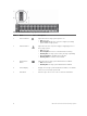
Figure 1. SCv2000/SCv2020 Storage System Front-Panel View Item Name 1 Power indicator Icon Description Lights when the storage system power is on. • • Off: No power On steady green: At least one power supply is providing power to the storage system 2 Status indicator Lights when at least one power supply is supplying power to the storage system.
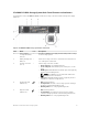
SCv2000/SCv2020 Storage System Back-Panel Features and Indicators The back panel of the SCv2000/SCv2020 contains the storage controller indicators and power supply indicators. Figure 2. SCv2000/SCv2020 Storage System Back-Panel View Item Name Icon 1 Power supply/ — cooling fan module (PSU) (2) Contains a 580 W power supply and fans that provide cooling for the storage system. 2 Battery backup unit — (BBU) (2) Allows the storage controller to shut down smoothly when a loss of AC power is detected.
Item Name 6 AC power status indicator (2) Icon Description • • • 7 DC power fault indicator (2) • • • Off: AC power is off, the power is on but the PSU is not in the storage system, or a hardware fault is possible Steady green: AC power is on Blinking green: AC power is on and the PSU is in standby mode Off: Normal operation Steady amber: PSU has been removed, a DC or other hardware fault has occurred, or the storage system is having a problem communicating with the PSU Blinking amber: PSU is in pr
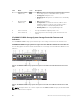
Item Control/Feature 1 Icon Description Battery status indicator 2 Battery fault indicator 3 MGMT port (Slot 3/Port 1) • • — • Blinking green (on 0.5 sec. / off 1.5 sec.): Battery heartbeat Fast blinking green (on 0.5 sec. / off 0.5 sec.
Item Control/Feature • • Four Fibre Channel ports (Slot 1/Port 1, Slot 1/Port 2, Slot 1/ Port 3, and Slot 1/ Port 4) with three LEDs per port Two Fibre Channel ports (Slot 1/Port 1 and Slot 1/Port 2) with three LEDs per port Icon Description • • • • • • • • All off: No power All on: Booting up Blinking amber: 2 Gbps activity Blinking green: 4 Gbps activity Blinking yellow: 8 Gbps activity Blinking amber and yellow: Beacon All blinking (simultaneous): Firmware initialized All blinking (alternating): Firm
Item Control/Feature 1 Icon Description Battery status indicator 2 Battery fault indicator 3 MGMT port (Slot 3/Port 1) • • — • Blinking green (on 0.5 sec. / off 1.5 sec.): Battery heartbeat Fast blinking green (on 0.5 sec. / off 0.5 sec.
Item Control/Feature • • Icon Description Four iSCSI ports (Slot 1/Port 1, Slot 1/Port 2, Slot 1/Port 3, and Slot 1/Port 4) with two LEDs per port Two iSCSI ports (Slot 1/Port 1 and Slot 1/ Port 2) with two LEDs per port • • Steady Amber: Link Blinking Green: Activity 15 Mini-SAS port B (Slot 2/ Port 2) Back-end expansion port B 16 Mini-SAS port A (Slot 2/ Port 1) Back-end expansion port A SCv2000/SCv2020 Storage System Storage Controller with Front-End SAS Ports The following figure shows the f
Item Control/Feature Icon Description NOTE: To use the RELP port as a front-end connection to host servers, a Flex Port license is required. 5 SAS activity indicators — There are four SAS PHYs per SAS port.
Figure 8. SCv2000/SCv2020 Storage System Drive Indicators Item Control/Feature Indicator Code 1 Drive activity indicator • • Blinking green: Drive activity Steady green: Drive is detected and has no faults 2 Drive status indicator • • • • Off: Normal operation Blinking amber (on 1 sec. / off 1 sec.): Drive identification is enabled Blinking amber (on 2 sec. / off 1 sec.
Replacing SCv2000/SCv2020 Storage System Components 2 This section describes how to remove and install components of the SCv2000/SCv2020 storage system. This information assumes that you have received the replacement component and are ready to install it. Safety Precautions Always follow these safety precautions to avoid injury and damage to Storage Center equipment.
• Provide a suitable power source with electrical overload protection. All Storage Center components must be grounded before applying power. Make sure that there is a safe electrical earth connection to power supply cords. Check the grounding before applying power. • The plugs on the power supply cords are used as the main disconnect device. Make sure that the socket outlets are located near the equipment and are easily accessible.
NOTE: To ensure proper storage system cooling, hard drive blanks must be installed in any hard drive slot that is not occupied. Pre-Replacement Procedures Perform the procedures described in this section before replacing a component of the SCv2000/ SCv2020 storage system. Send Diagnostic Data Using Dell SupportAssist Use Dell SupportAssist to send diagnostic data to Dell Technical Support Services. 1. Use the Storage Client to connect to the Storage Center. 2.
Shutting Down the Storage System If you are replacing the storage system chassis or rack rails, use the Dell Storage Client to shut down the storage system. About this task CAUTION: Shutting down the storage system results in a system outage. Steps 1. Select Actions → System → Shutdown/Restart. The Shutdown/Restart dialog box appears. 2. Select Shutdown Controller from the first drop-down menu. 3. Click OK.
Replacing Power Supply/Cooling Fan Modules The SCv2000/SCv2020 storage system supports two hot-swappable power supply/cooling fan modules. The cooling fans that cool the storage system and the power supplies are integrated into the power supply/cooling fan module and cannot be replaced separately. If one power supply/cooling fan module fails, the second module continues to provide power to the storage system.
Figure 11. Rear View of the Enclosure Showing the Failed Power Supply Identifying the Failed Cooling Fan To determine which cooling fan failed, use the Dell Storage Client. 1. Click the Hardware tab. 2. In the Hardware tab navigation pane, select and expand the failed storage system. 3. In the Hardware Alerts area, find the hardware alert that identifies the enclosure with the failed cooling fan.
Figure 12. Hardware Alert Identifying the Enclosure with the Failed Cooling Fan 4. In the Hardware tab navigation pane, expand the enclosure identified in the previous step. 5. Select Cooling Fan Sensors. The status of each cooling fan is displayed in the Cooling Fans tab. 6. Select the failed cooling fan. The location of the failed cooling fan is displayed in the Fan View tab. Figure 13.
Replacing a Power Supply/Cooling Fan Module Use this procedure to replace a failed power supply/cooling fan module. Prerequisites • Use SupportAssist to send diagnostic data to Dell Technical Support Services. About this task You can replace power supply/cooling fan modules one at a time without shutting down the storage system. Steps 1. Press the power switch on the power supply/cooling fan module to turn it off. 2.
Figure 15. Securing the Power Cable 6. Press the power switch on the power supply/cooling fan module to turn it on. NOTE: Allow several seconds for the storage system to recognize the power supply/cooling fan module and determine its status. When the power supply/cooling fan module is functioning properly, the AC power status indicator turns green and the three fault indicators are off. 7.
Figure 17. SCv2020 Storage System Drive Numbering Identifying the Failed Hard Drive To determine which hard drive failed, use the Dell Storage Client. 1. Start the Dell Storage Client and connect to the Storage Center that has an expansion enclosure with a failed hard drive. 2. Click the Hardware tab. 3. In the Hardware tab navigation pane, select and expand the Storage Center. 4. In the Hardware Alerts area, find the hardware alert that identifies the expansion enclosure with the failed hard drive.
Figure 19. Front View of the Expansion Enclosure Showing the Failed Hard Drive 8. (Optional) To open a wizard to guide you through the replacement steps, right-click on the failed hard drive. Replacing a Hard Drive Use this procedure to replace a failed hard drive. About this task Hard drives can be replaced one at a time without shutting down the storage system. NOTE: At least one powered drive must remain installed in the primary chassis when multiple disks are replaced. Steps 1.
Figure 20. Replacing a Hard Drive 5. 1. Hard drive carrier release handle 2. Hard drive indicators 3. Hard drive carrier 4. Hard drive slot Press the release button on the replacement hard drive to open the hard drive carrier release handle. NOTE: Hold the hard drive by the plastic part of the hard drive carrier or the handle. 6. Insert the hard drive carrier into the hard drive slot until the carrier make contact with the backplane.
Figure 21. Installing Dell Enterprise Hard Drives in a Storage System Steps 1. Remove the empty drive blank. 2. Open the hard drive carrier handle and insert the carrier into the hard drive slot. Start on the left side of the storage system with slot 0 and install drives from left to right. 3. Slide the drive into the slot until the hard drive carrier makes contact with the backplane. 4. Close the hard drive carrier handle to lock the hard drive in place. 5.
Figure 22. Replacing the Storage Controller Battery 1. Battery 3. Storage controller 2. Release tab 2. Align the replacement battery with the slot on the storage controller. 3. Slide the battery into the storage controller until the release tab clicks into place. Next steps Use SupportAssist to send diagnostic data to Dell Technical Support Services. Replacing a Storage Controller The SCv2000/SCv2020 storage system supports redundant hot-swappable storage controllers.
Figure 23. Hardware Alert Identifying the Enclosure with the Failed Storage Controller 4. In the Hardware tab navigation pane, expand the Enclosures entry. 5. Click I/O Modules. The status of each storage controller is displayed in the I/O Modules tab. 6. Select the failed storage controller to display its location in the IO Module View tab. Figure 24.
Replace a Single Storage Controller Use this procedure to replace a single failed storage controller. Prerequisites 1. Use SupportAssist to send diagnostic data to Dell Technical Support Services. 2. Shut down the storage controller using the Dell Storage Client. About this task Storage controllers can be replaced one at a time without shutting down the storage system. Steps 1. Make sure all of the cables are labeled. 2. Disconnect all of the cables from the storage controller that was shut down. 3.
10. Push the release lever toward the chassis until it clicks into place. The storage controller is powered on. NOTE: When a storage controller is powered on, a one‐minute delay occurs while the storage controller prepares to boot. During this time, the only indication that the storage controller is powered on are the LEDs on the storage controller. After the one‐minute delay, the fans and LEDs turn on to indicate that the storage controller is starting up. 11.
Figure 26. Replacing a Storage Controller 6. 1. Power supply/cooling fan module 3. Release lever 2. Storage controller Locate the battery removed earlier and insert it into the replacement storage controller. a. Align the battery with the slot on the storage controller. b. Slide the battery into the storage controller until the release tab clicks into place. 7. Insert the replacement storage controller into the chassis until it is fully seated. 8.
g. Click the Alerts tab. h. Right-click the alerts for the temperature sensor and I/O modules, then click Acknowledge. NOTE: The alerts may not appear immediately. If the alerts do not appear, wait 10 seconds and then click Refresh. 12. Clear the swap status for the temperature sensor and acknowledge the alert. a. b. c. d. e. f. Click the Hardware tab. In the Hardware tab navigation pane, expand the enclosure. Select Temperature Sensors.
Post-Replacement Procedures After replacing a component in the SCv2000/SCv2020 storage system, start up the storage system (if it was previously shut down) and use SupportAssist to send diagnostic data to Dell Technical Support Services. Then return the system to normal operation by disabling maintenance mode. Start Up the Storage Controller If the storage controller was previously shut down, perform this procedure to start it up. 1.
Troubleshooting SCv2000/SCv2020 Storage System Components 3 This section contains basic troubleshooting steps for components inside the SCv2000/SCv2020 storage systems. Troubleshooting Power Supply/Cooling Fan Modules To troubleshoot power supply/cooling fan modules: 1. Check the status of the power supply/cooling fan module using the Dell Storage Client. 2. Determine the status of the power supply/cooling fan module indicators.
Troubleshooting Storage Controllers To troubleshoot storage controllers: 1. Check the status of the storage controller using the Dell Storage Client. 2. Check the position of the storage controllers. The lower HSN should be on the top, and the higher HSN should be on the bottom. 3. Check the pins and reseat the storage controller. a. Remove the storage controller. b. Verify that the pins on the storage system backplane and the storage controller are not bent. c. Reinstall the storage controller. 4.
SCv2000/SCv2020 Storage System Technical Specifications 4 This section contains the technical specifications for SCv2000/SCv2020 storage systems. Technical Specifications The technical specifications for the SCv2000/SCv2020 storage systems are shown in the following tables. Drives SAS hard drives SCv2000: Up to 12 3.5-inch SAS hot-swappable hard drives (6.0 Gbps), six drive minimum SCv2020: Up to 24 2.5-inch SAS hot-swappable hard drives (6.
Back-Panel Port Connectors (per Storage Controller) Fibre Channel, iSCSI, or SAS connectors Connection to a Fibre Channel fabric, iSCSI network, or a direct connection to servers with SAS HBAs Ethernet connectors MGMT: 1 Gbps or 10 Gbps embedded Ethernet/iSCSI port used for Storage Center management REPL: 1 Gbps or 10 Gbps embedded iSCSI port used for replication to another Storage Center SAS connectors 6 Gbps SAS connectors for SAS port redundancy and additional expansion enclosures NOTE: SAS connecto
Available Hard Drive Power (per Slot) Supported hard drive power consumption (continuous) Up to 1.2 A at +5 V Up to 0.5 A at +12 V Physical Height 8.79 cm (3.46 in.) Width 48.2 cm (18.98 in.) Depth SCv2000: 57.6 cm (22.67 in.) SCv2020: 52.3 cm (20.59 in.) Weight (maximum configuration) SCv2000: 28.9 kg (63.9 lb) SCv2020: 24 kg (53 lb) Weight without drives SCv2000: 20.6 kg (45.4 lb) SCv2020: 18.
Environmental Storage –300 m to 12,000 m (–1000 ft to 39,370ft) Airborne Contaminant Level Class 42 G1 or lower as defined by ISA-S71.