SCv3000 和 SCv3020 存储系统 用户手册
注、小心和警告 注: “注”表示帮助您更好地使用该产品的重要信息。 小心: “小心”表示可能会损坏硬件或导致数据丢失,并告诉您如何避免此类问题。 警告: “警告”表示可能会导致财产损失、人身伤害甚至死亡。 © 2017 – 2018 Dell Inc. 或其子公司。保留所有权利。Dell、EMC 和其他商标是 Dell Inc. 或其附属机构的商标。其他商标可能是其各自所有者的商标。 2018 - 11 Rev.
目录 关于本手册....................................................................................................................................................... 5 修订历史记录.....................................................................................................................................................................5 读者对象.............................................................................................................................................................................
夹层卡..........................................................................................................................................................................31 机架导轨...........................................................................................................................................................................34 卸下机架导轨........................................................................................................................................................
序言 关于本手册 本手册介绍了 SCv3000 和 SCv3020 存储系统的功能和技术规格。 修订历史记录 说明文件编号:680-137-001 修订版 日期 说明 A 2017 年 10 月 初版 B 2018 年 4 月 添加缺失的 FRU C 2018 年 11 月 添加电源进线类型 读者对象 本手册中提供的信息面向 Dell 最终用户。 联系 Dell Dell 提供了几种联机和电话支持与服务选项。可用的选项因国家/地区和产品而不同,某些服务在您所在的区域可能并不提供。 要联系 Dell 以解决有关销售、技术支持或客户服务问题,请访问 Dell.
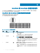
1 SCv3000 和 SCv3020 存储系统硬件 SCv3000 和 SCv3020 存储系统随附 Dell Enterprise Plus Value 驱动器、两个冗余电源设备/冷却风扇模块,以及两个冗余存储控制 器。每个存储控制器包含存储系统的前端、后端和管理通信端口。 SCv3000 和 SCv3020 存储系统前面板视图 存储系统的前面板包含电源和状态指示灯以及系统标识按钮。 此外,硬盘驱动器通过存储系统机箱的正面安装和卸下。 图 1: SCv3000 和 SCv3020 存储系统前面板视图 项目 名称 1 电源指示灯 图标 说明 当存储系统电源接通时亮起 • • 状态指示灯 2 熄灭 — 未通电 呈绿色稳定亮起 — 至少一个电源设备正在为存储系统供电 当两个存储控制器的启动过程均完成且未检测到故障时亮起。 注: 启动过程可能需要 5–10 分钟或更长时间才能完成。 • • • 标识按钮 3 呈蓝色闪烁(持续) — 用户已将一条命令发送到存储系统以让 LED 闪烁,使 得用户可以识别机架中的存储系统。 • • 6 SCv3000 和 SCv3020 存储系统硬件
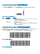
项目 名称 图标 说明 4 硬盘驱动器 — 最多可以有 30 个内置 2.5 英寸 SAS 硬盘驱动器 SCv3000 和 SCv3020 存储系统背面板视图 存储系统的背面板包含存储控制器指示灯和电源指示灯。 图 2: SCv3000 和 SCv3020 存储系统背面板视图 项目 名称 1 电源设备/冷却风扇模块 (2) 2 存储控制器(2 个) 图标 说明 包含一个电源设备和风扇(可为存储系统提供冷却功能),带有交流输入以提 供 200-240 伏特的电源。在 Storage Manager 中,背面板左侧的电源设备/冷却 风扇模块是电源设备 1。背面板右侧的电源设备/冷却风扇模块是电源设备 2。 — 每个存储控制器包含: • • • • • • 具有四个 SFP+ 端口或四个 RJ45 10GBASE-T 端口的可选 10 GbE iSCSI 夹层 卡 前端 I/O 卡的一个扩展插槽: – Fibre Channel – iSCSI – SAS SAS 扩展端口 — 从后端连接到扩展柜的两个 12 Gbps SAS 端口 USB 端口 — 一个 USB 2.
SCv3000 和 SCv3020 存储系统驱动器 SCv3000 和 SCv3020 存储系统支持 Dell Enterprise Plus Value 驱动器。 SCv3000 存储系统中的驱动器水平安装。SCv3020 存储系统中的驱动器垂直安装。驱动器上的指示灯提供状态和活动信息。 图 3: SCv300 和 SCv320 扩展柜驱动器指示灯 项目 控制/功能部件 1 驱动器活动指示灯 2 驱动器状态指示灯 指示灯代码 • • 呈绿色闪烁 – 驱动器具有 I/O 活动 呈绿色稳定亮起 – 检测到驱动器并且没有故障 • • 呈绿色稳定亮起 – 正常运行 呈绿色闪烁 - 已将一条命令发送到驱动器以让 LED 闪烁,使得您可以识别机架中的驱 动器。 呈琥珀色闪烁 – 硬件或固件故障 • SCv3000 和 SCv3020 存储系统驱动器编号 存储系统最多可容纳 16 或 30 个驱动器,从左上方驱动器为 0 开始,逐行从左到右编号。驱动器编号从左到右递增,然后从上到下 递增,因此第一行的驱动器从左到右编号为从 0 到 4,第二行的驱动器从左到右编号为从 5 到 9。 Storage
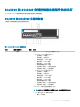
SCv3000 和 SCv3020 存储控制器功能部件和指示灯 SCv3000 和 SCv3020 存储系统在两个接口插槽中包含两个存储控制器。 SCv3000 和 SCv3020 存储控制器 下图显示了存储控制器上的功能部件和指示灯。 图 6: SCv3000 和 SCv3020 存储控制器 项目 控制/功能部件 1 I/O 卡插槽 图标 说明 Fibre Channel I/O 卡 — 端口从左到右编号为 1 到 4 • • 16 Gb Fibre Channel 端口上的 LED: – 全部熄灭 — 未通电 – 全部亮起 — 正在引导 – 琥珀色闪烁 — 4 Gbps 活动 – 绿色闪烁 — 8 Gbps 活动 – 黄色闪烁 — 16 Gbps 活动 – 琥珀色和黄色闪烁 — 信标 – 全部闪烁(同时) — 固件已初始化 – 全部闪烁(交替) — 固件故障 32 Gb Fibre Channel 端口上的 LED: – 全部熄灭 — 未通电 – 全部亮起 — 正在引导 – 琥珀色闪烁 — 8 Gbps 活动 – 绿色闪烁 — 16 Gbps 活动 – 黄色闪烁 — 32 Gbps 活动
项目 控制/功能部件 图标 说明 – – 持续琥珀色 — 链路 绿色闪烁 — 活动 SAS I/O 卡 - 端口从左到右编号为 1 到 4 SAS I/O 卡上的 SAS 端口没有 LED 指示灯。 标识 LED 2 呈蓝色闪烁(持续)— 存储系统 已将一条命令发送到存储系统以让 LED 闪 烁,使得您可以识别机架中的存储系统。 标识 LED 在机箱的控制面板上闪烁,使得用户查看机架前面即可找出存储系 统。 存储控制器上的标识 LED 也会闪烁,使得用户查看机架背面即可找出存储系 统。 3 高速缓存转闪存 (C2F) 4 运行状况 • • 熄灭 — 正常运行 呈绿色闪烁 — 使用电池运行(关闭) • • 熄灭 — 未接通电源 呈琥珀色闪烁 – 呈琥珀色慢速闪烁(2 秒亮起,1 秒熄灭)— 检测到控制器硬件故障。 使用 Storage Manager 查看有关硬件故障的具体详情。 – 呈琥珀色快速闪烁(每秒 4 次)— 电源正常,预操作系统正在引导 呈绿色闪烁 – 呈绿色缓慢闪烁(2 秒亮起,1 秒熄灭)— 操作系统正在引导 – 呈绿色闪烁(1 秒亮起,1 秒熄灭)— 系统处于安全
项目 控制/功能部件 图标 说明 • • 左侧 LED 呈琥珀色稳定亮起 — 链接(降级的速度) 右侧 LED 呈绿色闪烁 — 活动 注: 夹层卡不支持 DCB。 SCv3000 和 SCv3020 存储系统硬件 11
2 装回存储系统组件 本章介绍如何卸下和安装 SCv3000 和 SCv3020 存储系统的组件。此信息假定您已收到更换组件并已准备好安装。 安全防范措施 请始终遵循这些安全预防措施,以避免人身伤害和 Storage Center 设备损坏。 如果未按 Dell 指定的方式使用本指南中所述设备,则随设备提供的保护可能会受到影响。为了您的安全和人身保护,请遵守以下各节 所述规则。 注: 请参阅每个 Storage Center 组件随附的安全和法规信息。保修信息以独立文档形式提供。 安装安全防范措施 在安装 SCv3000 和 SCv3020 存储系统时,请遵循下列安全预防措施: • Dell 建议仅应让有机架安装经验的人员将 SCv3000 和 SCv3020 存储系统安装到机架。 • 在机架中安装多个扩展柜时,填装机架的顺序为从下到上,清空机架的顺序为从上到下。 • 机架结构必须支撑所安装扩展柜的总重量。其设计应具备适当的稳定功能,以防止机架在安装过程中或在正常使用时倾翻或被推 倒。 • 为了防止机架倾翻,一次只能将一个存储系统滑出机架外。 • 请确保存储系统始终完全接地,以防止静电放
静电放电防范措施 请始终遵循静电放电 (ESD) 防范措施,以避免发生人身伤害和 Storage Center 设备损坏。 静电放电 (ESD) 由带有不同电荷的两个对象相互接触而生成。所导致的放电可损坏电子组件和印刷电路板。请遵循以下原则,以避 免 ESD 对设备造成损害: • Dell 建议您在处理机箱的内部组件时始终使用防静电垫子和防静电腕带。 • 取放插件模块和组件时,请遵循所有常规的 ESD 防范措施。 • 使用合适的 ESD 腕带或踝带。 • 避免接触背板组件和模块连接器。 • 在准备好投入使用前,将所有组件和印刷电路板 (PCB) 放置在防静电包中。 一般安全防范措施 请始终遵循一般安全防范措施,以避免人身伤害和 Storage Center 设备损坏。 • 使存储系统机箱周围区域保持整洁有序。 • 将卸下的所有系统组件放置在远离存储系统机箱的地方,或者将其放在桌子上,使它们不会挡住其他人的道路。 • 操作存储系统机箱时,请勿穿戴宽松的衣物,如领带和扣子已解开的衬衫袖。这些物品可能会接触电路或被拉入冷却风扇中。 • 除去身上的所有珠宝或金属物体。这些物品是绝佳的
3 单击 常规选项卡。 4 在操作模式字段中选择维护。选择维护会将警报与正常工作期间发生的事件相隔离。 5 单击确定。 关闭存储系统和扩展柜 如果更换组件不支持热插拔,可使用 Dell Storage Manager 关闭存储系统和扩展柜。关闭存储系统和扩展柜会导致系统停机,因此请 计划在维护时段执行这些步骤。 前提条件 在关闭存储系统和扩展柜前,请执行以下任务: 1 识别要更换的部件。 2 找到更换部件。 3 确保备齐更换部件所需的工具。 步骤 1 在“操作”菜单中,选择系统→关闭/重新启动。此时会打开关闭/重新启动对话框。 2 从 Storage Center 应该做什么?下拉菜单中,选择 关闭。 挡板 前挡板是 SCv3000 和 SCv3020 存储系统的前面板的护盖。 卸下前挡板 在存储系统中卸下或安装硬盘驱动器之前,请卸下前挡板。 1 使用系统钥匙打开挡板左端的锁扣。 2 向上提起锁扣旁的释放闩锁。 3 旋转挡板的左端,使其脱离前面板。 4 将挡板右端从挂钩上卸下,拉动挡板使其脱离存储系统。 14 装回存储系统组件
图 7: 安装和卸下挡板 1 锁扣 2 前挡板 安装前挡板 为了固定存储系统,须安装前挡板。 1 将更换挡板的右端勾在存储系统的前面板上。 2 将挡板左端插入固定插槽,直至释放闩锁锁入到位。 3 使用锁扣固定挡板。 硬盘驱动器 SCv3000 和 SCv3020 存储系统支持热插拔硬盘驱动器。 最少必须在机箱或扩展柜中安装 4 个 SSD 或 7 个驱动器。SCv3000 和 SCv3020 存储系统最多支持在机箱中安装 16 或 30 个驱动 器。驱动器先从左到右再从上到下安装。第一行的驱动器从左到右编号为从 0 到 4,第二行的驱动器从左到右编号为从 5 到 9,以此 类推。 Dell Storage Manager 将驱动器标识为 XX-YY,其中 XX 是存储系统的设备 ID 编号,YY 是存储系统内部的驱动器位置。 图 8: SCv3000 存储系统驱动器编号 装回存储系统组件 15
图 9: SCv3020 存储系统驱动器编号 识别故障驱动器 要确定是哪一个驱动器发生故障,请使用 Dell Storage Manager。 1 单击硬件选项卡。 2 在硬件选项卡导航窗格中,选择机柜节点。 3 单击 Disks(磁盘)选项卡。 4 查找状态为 Down 的驱动器。 5 从名称列中记下驱动器的位置。 卸下故障驱动器 使用此过程从 SCv3000 和 SCv3020 存储系统中卸下发生故障的驱动器。 前提条件 • 卸下驱动器之前,请确保以下警报将显示在 Dell Storage Manager 的警报选项卡中: Drive # is ready to be removed.
2 使用 Dell Storage Manager 编辑 Storage Center 设置并将 Storage Center 的操作模式设置为生产模式。 3 使用 Dell Storage Manager 将 SupportAssist 信息发送至技术支持。 电源设备和冷却风扇模块 SCv3000 和 SCv3020 存储系统支持两个可热插拔的电源设备/冷却风扇模块。 冷却存储系统的冷却风扇和电源设备均集成到电源设备/冷却风扇模块中且不能单独进行更换。如果一个电源设备/冷却风扇模块出现 故障,则第二个模块继续为存储系统供电。 注: 电源设备/冷却风扇模块出现故障时,另一个模块中的冷却风扇速度会显著提高,从而提供充足的冷却。安装新的电源设备/ 冷却风扇模块后,冷却风扇速度将逐渐降低。 小心: 可以从处于通电状态下存储系统中卸下单个电源设备/冷却风扇模块不超过 90 秒。如果卸下电源设备/冷却风扇模块超过 90 秒,存储系统可能会自动关闭以防止损坏。 识别故障电源设备 要确定是哪一个电源设备发生故障,请使用 Dell Storage Manager。 1 单击硬件选项卡。 2 在硬件选项卡导航窗
图 10: 从电源电缆中卸下钩环紧固带 3 向右按电源设备/冷却风扇模块上的释放卡舌,然后使用手柄将该模块滑出机箱。 小心: 电源设备/冷却风扇模块很重。为避免受伤,请用双手卸下模块。 图 11: 卸下电源设备/冷却风扇模块 1 电源设备/冷却风扇模块 2 电源插槽 3 释放卡舌 4 电源设备/冷却风扇模块 LED 手柄 5 电源开关 4 将更换的电源设备/冷却风扇模块滑入机箱中,直至其完全就位且释放卡舌卡入到位。 5 将电源电缆连接至电源设备/冷却风扇模块,并确保将电缆插头插入电源插座。 6 使用钩环紧固带固定电源电缆。 7 按下电源设备/冷却风扇模块上的电源开关以将其打开。 注: 等待几秒钟,以便存储系统识别电源设备/冷却风扇模块并确定其状态。在电源设备/冷却风扇模块正常运行后,交流电 源状态指示灯变为绿色,电源设备/冷却风扇状态指示灯熄灭。 8 在 Dell Storage Manager 中,确保更换电源设备被识别并显示为正常运行。 18 装回存储系统组件
下一步 1 使用 Dell Storage Manager 编辑 Storage Center 设置并将 Storage Center 的操作模式设置为生产模式。 2 使用 Dell Storage Manager 将 SupportAssist 信息发送至技术支持。 存储控制器 使用此过程从机箱中卸下存储控制器。 如果存储控制器发生故障,或者如果存储控制器内部的组件发生故障,请卸下存储控制器。 小心: 每个存储控制器的护盖上的标签指示要安装存储控制器的插槽。存储控制器 1 必须安装在上方插槽中。存储控制器 2 必须 安装在下方插槽中。如果将存储控制器安装到错误的插槽中,Storage Center 将无法正常运行。 拆装存储控制器内部组件之前 拆装存储控制器内部组件之前,首先执行以下步骤: 1 使用 Dell Storage Manager 编辑 Storage Center 设置并将 Storage Center 的操作模式设置为维护模式。 2 使用 Dell Storage Manager 关闭存储控制器。 3 从机箱中卸下存储控制器。 4 卸下存储控制器之后,请立即将维修挡板安
图 12: 安装维修挡板 存储控制器 每个存储控制器均包含存储系统的前端、后端和管理通信端口。 卸下存储控制器 使用此过程从机箱中卸下存储控制器。 前提条件 1 找到存储控制器维修挡板。 2 使用 Dell Storage Manager 将 SupportAssist 信息发送至技术支持。有关更多信息,请参阅 Storage Manager Administrator’s Guide (Storage Manager 管理员指南)。 小心: 为了防止存储系统热关机,必须在卸下存储控制器三分钟内安装维修挡板。 关于此任务 您可以在不关闭存储系统的情况下一次更换一个 存储控制器。 步骤 1 使用 Dell Storage Manager 关闭存储控制器。 2 确保标记好已插入到存储控制器中的所有电缆。 3 从已关闭存储控制器中拔下所有电缆。 4 按下存储控制器上的释放卡舌。 5 转动释放杆,使之与存储控制器分离。 6 抓住释放拉杆,然后将存储控制器从机箱中部分拉出。 7 用双手抓住存储控制器的两侧,然后将存储控制器完全从机箱中拉出。 20 装回存储系统组件
图 13: 卸下和安装存储控制器 8 1 SCv3000 和 SCv3020 存储系统机箱 3 释放拉杆 2 存储控制器 将维修挡板安装到存储系统机箱内空的插槽中。 安装存储控制器 将存储控制器安装到存储系统机箱中。 关于此任务 存储控制器的护盖表示存储控制器在哪个插槽中运行。 • • 存储控制器 1 应插入上方插槽中。 存储控制器 2 应插入下方插槽中。 步骤 1 从机箱插槽中卸下维修挡板。 小心: 为了防止存储系统热关机,必须在卸下维修挡板三分钟内安装存储控制器。 2 用双手抓住存储控制器的两侧,然后将它放在机箱上打开的插槽中。 3 将存储控制器推入到插槽中。 4 朝机箱方向推动释放拉杆,直至存储控制器卡入到位。 存储控制器电源开启并引导。 注: 如果存储控制器上的 Storage Center 软件版本早于现有 存储控制器上的软件版本,存储系统将为存储控制器更新至现有 存储控制器上的软件版本。存储控制器上的 Storage Center 软件更新可能需要 15 到 45 分钟的时间。 5 将所有电缆重新连接至存储控制器。 6 使用 Dell Storage Man
更换故障存储控制器 用可换的存储控制器更换故障存储控制器。 先决条件 小心: 请不要关闭两个存储控制器。当故障存储控制器关闭时,另一个存储控制器将继续运行。当两个存储控制器被错误关闭 时,请在更换故障存储控制器之前,重启存储系统。 关于此任务 存储控制器的护盖表示存储控制器在哪个插槽中运行。 • 存储控制器 1 应插入上方插槽中。 • 存储控制器 2 应插入下方插槽中。 步骤 1 确保标记好已插入到存储控制器中的所有电缆。 2 断开电缆与存储控制器的连接。 3 从机箱中卸下故障存储控制器。 4 将维修挡板安装到机箱内的空插槽中。 5 在故障存储控制器上执行以下以下操作: 小心: 为了防止存储系统热关机,必须在卸下存储控制器三分钟内安装维修挡板。 a 从存储控制器上取下护盖,并将其放在一旁。 b 护盖上的标签标识出要从中拆卸故障存储控制器的机箱插槽。 从故障存储控制器上卸下 I/O 卡、夹层卡和电池备用装置。 在存储控制器中重新安装 I/O 卡、夹层卡和电池备用装置。 6 在更换存储控制器上执行以下操作: 从存储控制器中卸下盖子。 将 I/O 卡、夹层卡和电池备用装置插入至存
存储控制器的护盖 存储控制器的护盖保护存储控制器的内部组件。 卸下存储控制器的护盖 卸下存储控制器的护盖以访问内部的组件。 1 按下存储控制器护盖上的蓝色触点并将护盖向后滑动。 2 抓住护盖两侧,小心地从存储控制器上提起护盖。 小心: 在没有护盖的情况下,请勿操作存储控制器。在护盖打开的情况下,请勿将存储控制器滑回机箱中。 图 14: 卸下和安装存储控制器的护盖 1 存储控制器的护盖 3 存储控制器 2 存储控制器的闩锁触点 更换存储控制器的护盖 在将存储控制器重新插入至存储系统机箱前,更换其护盖。 1 将护盖放在存储控制器的顶部。 2 将护盖朝存储控制器背面滑动,直至其卡入到位。 装回存储系统组件 23
小心: 在没有护盖的情况下,请勿操作存储控制器。 图 15: 卸下存储控制器的护盖 1 存储控制器的护盖 3 存储控制器 2 存储控制器的闩锁触点 电池备用装置 在两个存储控制器之间镜像写入高速缓存。如果发生电源故障,电池备用装置可为存储控制器提供电源,以便可以将写入高速缓存保 存到存储控制器内的 SSD 中。 如果电池备用装置开始发生故障,请予以更换。 卸下电池备用装置 使用此过程卸下电池备用装置。 先决条件 • 使用 Dell Storage Manager 将 SupportAssist 信息发送至技术支持。 • 使用 Dell Storage Manager 编辑 Storage Center 设置并将 Storage Center 的操作模式设置为维护模式。 步骤 1 使用 Dell Storage Manager 关闭存储控制器。 2 确保标记好已插入到存储控制器中的所有电缆。 3 从已关闭的存储控制器中拔下电缆。 4 从机箱中卸下存储控制器 24 装回存储系统组件
小心: 为了防止存储系统热关机,必须在卸下存储控制器三分钟内安装维修挡板。 5 将维修挡板安装到机箱内的空插槽中。 6 验证存储控制器上的电池 LED 熄灭。可能要经过几秒钟之后 LED 才会熄灭。 7 从存储控制器中卸下盖子。 8 向上提起电池备用装置中的手柄。电池便会从固定框架连接器中滑出。 图 16: 卸下电池备用装置 1 电池备用装置 3 固定框架电池连接器 2 电池固定框架 安装电池备用装置 使用此过程安装电池备用装置。 步骤 1 在存储控制器中放置电池备用装置,直到盖住固定框架。 2 压低手柄,直至它与电池平齐。 电池将滑入到固定框架连接器中。 3 从机箱中卸下维修挡板。 小心: 为了防止存储系统热关机,必须在卸下维修挡板三分钟内安装存储控制器。 4 将存储控制器安装到机箱中。 5 将电缆重新连接至存储控制器。 6 从 Dell Storage Manager 的硬件选项卡中清除存储控制器交换状态。 有关说明,请参阅 Storage Manager Administrator’s Guide(Storage Manager 管理员指南)。 装回存储系
下一步 • 使用 Dell Storage Manager 编辑 Storage Center 设置并将 Storage Center 的操作模式设置为生产模式。 • 使用 Dell Storage Manager 将 SupportAssist 信息发送至技术支持。 提升板 1 当要更换 SCv3000 和 SCv3020 存储系统的某些组件时,您可能需要卸下提升板。 更换提升卡时请遵循正确的静电放电防范措施。 卸下提升板 1 使用此过程卸下提升板 1。 先决条件 • 使用 Dell Storage Manager 将 SupportAssist 信息发送至技术支持。 • 使用 Dell Storage Manager 编辑 Storage Center 设置并将 Storage Center 的操作模式设置为维护模式。 步骤 1 使用 Dell Storage Manager 关闭存储控制器。 2 确保标记好已插入到存储控制器中的所有电缆。 3 从已关闭的存储控制器中拔下电缆。 4 从机箱中卸下存储控制器。 小心: 为了防止存储系统热关机,必须在卸下存储控制器三分钟内安装维修挡
图 17: 卸下提升板 1 1 提升板 1 3 定位插销(2 个) 2 定位插销套(2 个) 安装提升板 1 使用此过程安装提升板 1。 先决条件 将 I/O 卡安装到提升板中。 步骤 1 使用板上的定位销子和提升板上的定位套将提升板放置在连接器上方。 2 放入提升板,直至提升板在连接器中完全就位。 3 压低蓝色闩锁以将提升板固定到机箱。 4 更换存储控制器的护盖。 5 从机箱中卸下维修挡板。 6 将存储控制器安装到机箱中。 7 将电缆重新连接至存储控制器。 8 从 Dell Storage Manager 的硬件选项卡中清除存储控制器交换状态。 小心: 为了防止存储系统热关机,必须在卸下维修挡板三分钟内安装存储控制器。 有关说明,请参阅 Storage Manager Administrator’s Guide(Storage Manager 管理员指南)。 后续步骤 1 使用 Dell Storage Manager 编辑 Storage Center 设置并将 Storage Center 的操作模式设置为生产模式。 装回存储系统组件 27
2 使用 Dell Storage Manager 将 SupportAssist 信息发送至技术支持 I/O 卡 存储控制器在一个 PCI 插槽中支持单 I/O 卡。 以下类型的 I/O 卡可用于前端连接: • Fibre Channel • iSCSI • SAS 从提升板 1 中卸下 I/O 卡 使用此过程卸下提升板 1 中的 I/O 卡。 前提条件 • 使用 Dell Storage Manager 将 SupportAssist 信息发送至技术支持。 • 使用 Dell Storage Manager 编辑 Storage Center 设置并将 Storage Center 的操作模式设置为维护模式。 步骤 1 使用 Dell Storage Manager 关闭存储控制器。 2 确保标记好已插入到存储控制器中的所有电缆。 3 从已关闭的存储控制器中拔下电缆。 4 从机箱中卸下存储控制器 小心: 为了防止存储系统热关机,必须在卸下存储控制器三分钟内安装维修挡板。 5 将维修挡板安装到机箱内的空插槽中。 6 卸下存储控制器的护盖。 7 提起用于将提升板固
图 18: 从提升板 1 中卸下 I/O 卡 1 I/O 卡 2 闩锁 3 指旋螺钉 4 固定器 在提升板 1 中安装 I/O 卡 使用此过程在提升板 1 中安装 I/O 卡。 步骤 1 打开更换 I/O 卡的包装并做好安装的准备。有关说明,请参阅 I/O 卡附带的说明文件。 2 握住 I/O 卡的边缘,调整卡的位置,使卡式边缘连接器与提升板上的 I/O 卡连接器对齐。 装回存储系统组件 29
图 19: 提升板 1 上的 I/O 卡连接器位置 1 3 卡连接器 将卡式边缘连接器稳固地插入 I/O 卡连接器,直至插卡完全就位。 小心: 确保 I/O 卡在 I/O 卡连接器中完全就位。如果 I/O 卡未与连接器充分接触,可能会导致 SCv3000 和 SCv3020 存储系 统中出现不可预知的故障。 4 摆动 I/O 卡固定器,以使固定器与 I/O 卡的背面平齐。 图 20: 在提升板 1 中安装 I/O 卡 1 I/O 卡 2 闩锁 3 指旋螺钉 4 固定器 5 合上 I/O 卡闩锁。 6 拧紧固定器背面的蓝色指旋螺钉,将 I/O 卡固定到位。 7 将提升板插入到存储控制器中。 30 装回存储系统组件
8 压低闩锁,以将提升板固定到位。 9 更换存储控制器的护盖。 10 从机箱中卸下维修挡板。 11 将存储控制器安装到机箱中。 12 将电缆重新连接至存储控制器。 13 从 Dell Storage Manager 的硬件选项卡中清除存储控制器交换状态。 小心: 为了防止存储系统热关机,必须在卸下维修挡板三分钟内安装存储控制器。 有关说明,请参阅 Storage Manager Administrator’s Guide(Storage Manager 管理员指南)。 后续步骤 1 使用 Dell Storage Manager 编辑 Storage Center 设置并将 Storage Center 的操作模式设置为生产模式。 2 使用 Dell Storage Manager 将 SupportAssist 信息发送至技术支持。 夹层卡 请按照以下步骤,安装或更换夹层卡。在添加或更换夹层卡时遵守正确的静电释放的预防措施。夹层卡可以有 SFP+ 连接或 RJ-45 连 接,具体视客户规格而定。 卸下挡片插槽护盖或夹层卡 使用此过程卸下挡片插槽护盖或现有的夹层卡。 先决条
图 21: 卸下夹层卡 1 夹层卡 2 螺钉 3 触点 4 连接器 5 释放闩锁 9 (仅现有的夹层卡)按下释放闩锁并提起夹层卡的后端,直至其脱离连接器。 10 从存储控制器中卸下挡片插槽护盖或夹层卡。 安装夹层卡 使用此过程安装夹层卡。 步骤 1 使夹层卡前端以一定的角度放入到存储控制器前面的插槽中。 32 装回存储系统组件
图 22: 安装夹层卡 1 夹层卡 2 螺钉 3 接触点(蓝色点) 4 连接器 5 释放闩锁 2 同时将释放闩锁和夹层卡背面的蓝色点向下按,直至夹层卡固定在连接器中。 3 插入并拧紧能将夹层卡固定到存储控制器的螺钉。 4 将提升板 1 装回存储控制器中。 5 更换存储控制器的护盖。 6 从机箱中卸下维修挡板。 小心: 为了防止存储系统热关机,必须在卸下维修挡板三分钟内安装存储控制器。 7 将存储控制器安装到机箱中。 8 将电缆重新连接至存储控制器。 9 从 Dell Storage Manager 的硬件选项卡中清除存储控制器交换状态。 有关说明,请参阅 Storage Manager Administrator’s Guide(Storage Manager 管理员指南)。 后续步骤 1 使用 Dell Storage Manager 编辑 Storage Center 设置并将 Storage Center 的操作模式设置为生产模式。 2 如果您已将夹层卡添加到空置的夹层卡插槽,请使用 Dell Storage Manager 来配置新容错域。
机架导轨 机架导轨用于将存储控制器安装到机架中。 卸下机架导轨 前提条件 1 使用 SupportAssist 将诊断数据发送至 技术支持。 2 使用 Storage Manager Client 关闭存储系统。 关于此任务 注: 更换机架导轨必须在计划的维护时段进行,此时 Storage Center 系统在网络中不可用。 步骤 1 确保所有电缆都贴上标签。 2 断开所有电缆与存储系统的连接。 3 拧松机箱吊耳中将机箱固定至机架的螺钉。 图 23: 拧松螺钉 4 从机架中卸下存储系统。 5 从机架中卸下机架导轨。 34 装回存储系统组件
安装机架导轨 执行下列步骤以安装 SCv3000 和 SCv3020 存储系统的机架导轨。 步骤 1 将更换的机架导轨安装到机架中。 2 将存储系统安装到机架中。 3 拧紧机箱吊耳中将机箱固定至机架的螺钉。 图 24: 拧紧螺钉 4 将电缆重新连接至存储系统。 5 启动存储系统。 下一步 使用 SupportAssist 将诊断数据发送至 技术支持。 启动 Storage Center 硬件 执行这些步骤以在关闭硬件或断电后启动 Storage Center 硬件。 关于此任务 如果 Storage Center 硬件包括扩展柜,请先打开扩展柜,然后再打开存储系统。 步骤 1 将存储系统和任何扩展柜连接到电源。 2 开启任何连接至 Storage Center 的扩展柜。 注: 扩展柜开启后,其 ID 号显示在背面板上。如果您想扩展柜的 ID 按顺序出现,请以您想要 ID 显示的顺序逐个开启扩展 柜。 a 同时按下扩展柜背面板上的两个电源开关,以开启扩展柜。 当扩展柜通电并且运行时,扩展柜正面的状态指示灯变为蓝色。 装回存储系统组件 35
b 3 打开连接至 Storage Center 的任何其他扩展柜。等每个扩展柜开始运行时,再打开下一个扩展柜。 当所有扩展柜已开启后,通过按下机箱背面的两个电源开关以打开存储系统。 36 装回存储系统组件
3 SCv3000 和 SCv3020 存储系统技术规格 本附录包含 SCv3000 和 SCv3020 存储系统的技术规格。 技术规格 以下表格显示 SCv3000 和 SCv3020 存储系统的技术规格。 驱动器 SAS 硬盘驱动器 SCv3000 最多 16 个 3.5 英寸热插拔硬盘驱动器 (12GB SAS) SCv3020 最多 30 个 2.
LED 指示灯 硬盘驱动器托架 存储控制器 电源设备/冷却风扇 • 具有单色 LED 的识别按钮 • • 一个单色活动 LED 每个驱动器具有一个双色 LED 状态指示灯 • • • • • 每个以太网端口有两个单色 LED,用于表示活动和链路速度 每个 SAS 连接器有一个双色 LED,用于表示端口活动和状态 一个表示状态的单色 LED 一个表示系统故障的单色 LED 一个用于标识系统的单色 LED 一个双色 LED 手柄,指示电源设备和冷却风扇状态 电源设备 (PSU) 交流电源设备(每个电源设备) PSU 类型 1 PSU 类型 2(仅限日本) PSU 类型 3 最大输出功率 1485 W 1485 W 1378 W 最大输入电源 1688 W 1707 W 1584 W 最大输入电流 8.8 A 17.
环境参数 有关特定存储系统配置的环境测量值的附加信息,请参阅 dell.com/environmental_datasheets。 温度 运行时 10°C (50°F) 至 35°C (95°F),最大温度变化梯度为 20°C/小时(36°F/小时) 在高于 35°C 的情况下运行会导致数据丢失 存储 –40° 至 65°C(–40° 至 149°F)/最高海拔 12,000 米(39,370 英尺) 相对湿度 运行时 最大露点为 29°C (84.2°F) 时,相对湿度为 10% 至 80%(非冷凝) 存储 最大露点为 33°C (91°F) 时,相对湿度为 5% 至 95%(非冷凝) 最大振动 运行时 5–350 Hz 时,0.26 Grms(全部操作方向) 存储 10-500 Hz 时,1.88 Grms,可持续 15 分钟(被测的所有六面) 最大撞击 运行时 31 G +/- 5%,脉冲宽度为 2.