
Owners Manual


Item Name Icon Description
3 Identication button Blinking blue continuously – A user sent a command to the storage system to
make the LED blink so that the user can identify the storage system in the rack.
• The identication LED blinks on the control panel of the chassis, to allow users
to nd the storage system when looking at the front of the rack.
• The identication LEDs on the storage controllers also blink, which allows users
to nd the storage system when looking at the back of the rack.
4 Hard drives — Can have up to 30 internal 2.5-inch SAS hard drives
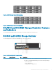
SCv3000 and SCv3020 Storage System Back-Panel
View
The back panel of the storage system contains the storage controller indicators and power supply indicators.
Figure 2. SCv3000 and SCv3020 Storage System Back-Panel View
Item
Name Icon Description
1 Power supply/cooling fan
module (2)
Contains power supplies and fans that provide cooling for the storage system, with
AC input to the power supply of 200–240 V. In Storage Manager, the power
supply/cooling fan module on the left side of the back panel is Power Supply 1 and
power supply/cooling fan module on the right side of the back panel is Power
Supply 2.
2 Storage controller (2) — Each storage controller contains:
• Optional 10 GbE iSCSI mezzanine card with four SFP+ ports or four RJ45
10GBASE-T ports
• One expansion slot for a front-end I/O card:
– Fibre Channel
– iSCSI
– SAS
• SAS expansion ports – Two 12 Gbps SAS ports for back-end connectivity to
expansion enclosures
• USB port – Single USB 2.0 port
• MGMT port – Embedded Ethernet port for system management
• Serial port – Micro-USB serial port used for an alternative initial conguration
and support-only functions
3 Power switch (2) — Controls power for the storage system. Each power supply/cooling fan module has
one power switch.
SCv3000 and SCv3020 Storage System Hardware 7