
Owners Manual


Item Name Icon Description
4 Power supply/cooling fan
module LED handle
—
The handle of the power supply/cooling fan module indicates the DC power status
of the power supply and the fans.
• Not lit – No power
• Solid green – Power supply has valid power source and is operational
• Blinking amber – Error condition in the power supply
• Blinking green – Firmware is being updated.
• Blinking green then o – Power supply mismatch
5 Power socket (2) — Accepts the following standard computer power cords:
• IEC320-C13 for deployments worldwide
• IEC60320-C19 for deployments in Japan
SCv3000 and SCv3020 Storage System
Drives
The SCv3000 and SCv3020 storage system supports Dell Enterprise Plus Value drives.
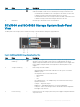
The drives in an SCv3000 storage system are installed horizontally. The drives in an SCv3020 storage system are installed vertically. The
indicators on the drives provide status and activity information.
Figure 3. SCv300 and SCv320 Expansion Enclosure Drive Indicators
Item
Control/Feature Indicator Code
1 Drive activity indicator
• Blinking green – Drive has I/O activity
• Steady green – Drive is detected and has no faults
2 Drive status indicator
• Steady green – Normal operation
• Blinking green – A command was sent to the drive to make the LED blink so that you can
identify the drive in the rack.
• Blinking amber – Hardware or rmware fault
SCv3000 and SCv3020 Storage System Drive
Numbering
The storage system holds up to 16 or 30 drives, which are numbered from left to right in rows starting from 0 at the top-left drive. Drive
numbers increment from left to right, and then top to bottom such that the rst row of drives is numbered from 0 to 4 from left to right,
and the second row of drives is numbered from 5 to 9 from left to right.
Storage Manager identies drives as XX-YY, where XX is the number of the unit ID of the storage system and YY is the drive position
inside the storage system.
8
SCv3000 and SCv3020 Storage System Hardware