
Owners Manual


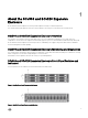


Table Of Contents
- Dell SCv300 and SCv320 Expansion Enclosure Owner's Manual
- About this Guide
- About the SCv300 and SCv320 Expansion Enclosure
- SCv300 and SCv320 Expansion Enclosure Overview
- SCv300 and SCv320 Expansion Enclosure Monitoring and Diagnostics
- SCv300 and SCv320 Expansion Enclosure Front-Panel Features and Indicators
- SCv300 and SCv320 Expansion Enclosure Back-Panel Features and Indicators
- SCv300 and SCv320 Expansion Enclosure EMM Features and Indicators
- SCv300 and SCv320 Expansion Enclosure Drives
- Replacing SCv300 and SCv320 Expansion Enclosure Components
- Troubleshooting SCv300 and SCv320 Components
- SCv300 and SCv320 Expansion Enclosure Technical Specifications

Item Name Description
5 Power switches (2) Controls power for the expansion enclosure. There is one switch for each
power supply.
6 Power supply unit and cooling fan
module (PS2)
600 W power supply
SCv300 and SCv320 Expansion Enclosure EMM Features and
Indicators
The SCv300 and SCv320 includes two enclosure management modules (EMMs) in two interface slots.
Figure 4. SCv300 and SCv320 Expansion Enclosure EMM Features and Indicators
Item
Name Icon Description
1 SAS port status
(1–4)
• Green: All the links to the port are connected
• Amber: One or more links are not connected
• O: Expansion enclosure is not connected
2 EMM status
indicator
• On steady green: Normal operation
• Amber: Expansion enclosure did not boot or is not properly congured
• Blinking green: Automatic update in progress
• Blinking amber (two times per sequence): Expansion enclosure is unable to
communicate with other expansion enclosures
• Blinking amber (four times per sequence): Firmware update failed
• Blinking amber (ve times per sequence): Firmware versions are dierent
between the two EMMs
3 SAS ports 1–4
(Input or Output)
Provides SAS connections for cabling the storage controller to the next expansion
enclosure in the chain. (Single Port, Redundant, and Multi-chain Conguration).
4 USB Mini-B (serial
debug port)
Not for customer use.
5 Unit ID display Displays the enclosure ID.
EMM Failover
Control and monitoring of the expansion enclosure elements can be transferred from one EMM to another in the event of an EMM
failure.
In the event of an EMM failure, the functioning EMM activates the amber status LED of the failed EMM. The functioning EMM then
manages all aspects of the expansion enclosure, including monitoring and controlling the expansion enclosure LEDs, power supply
units, and fans.
7