SCv360 Expansion Enclosure Getting Started Guide Regulatory Model: CYAE
Notes, Cautions, and Warnings NOTE: A NOTE indicates important information that helps you make better use of your product. CAUTION: A CAUTION indicates either potential damage to hardware or loss of data and tells you how to avoid the problem. WARNING: A WARNING indicates a potential for property damage, personal injury, or death. © 2017 – 2018 Dell Inc. or its subsidiaries. All rights reserved. Dell, EMC, and other trademarks are trademarks of Dell Inc. or its subsidiaries.
Setting Up the Expansion Enclosure Consider the following best practices when setting up an SCv360 expansion enclosure: • An SCv360 expansion enclosure is shipped with two SAS cables. Two more SAS cables are needed to connect an SCv360 expansion enclosure to a storage system in a highavailability environment. The SAS cables can be ordered in lengths of three, four, or five meters. • Before connecting any cables between the expansion enclosure and storage system, physically label each port and connector.
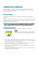
Installation and Configuration Before you begin the installation, make sure that the site where you plan to install the expansion enclosure has standard power from an independent source or a rack power distribution unit (PDU) with a UPS. Safety Precautions Always follow these safety precautions to avoid injury and damage to Storage Center equipment. If equipment described in this guide is used in a manner not specified by Dell, the protection provided by the equipment could be impaired.
• The rack construction must support the total weight of the installed expansion enclosures. The design should incorporate stabilizing features suitable to prevent the rack from tipping or being pushed over during installation or in normal use. • To prevent the rack from tipping, slide only one expansion enclosure out of the rack at a time. • Make sure that the expansion enclosure is always fully grounded to prevent damage from electrostatic discharge.
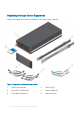
Unpacking Storage Center Equipment Unpack the expansion enclosure and identify the items in your shipment. Figure 1.
Determine the Mounting Location Determine where to mount the SCv360 expansion enclosure in the rack. 1 Identify a location in the rack with 4U of space for the expansion enclosure. WARNING: If you plan to install the expansion enclosure above the lower 20U of a rack, use a mechanical lift to avoid injury. 2 If you plan to install the 1U cable management tray below the expansion enclosure, identify a location in the rack with 5U of space for the expansion enclosure and cable management tray. Figure 2.
Table 1. Standard Rail Kit Part Part Number Description 106-002-452 M5-0.8 x 10 mm Phillips pan-head SEMS screw (Quantity: 2) Used to secure the expansion enclosure rails to the front of the rack 106-002-453 M5-0.8 x 16 mm Phillips pan-head SEMS screw (Quantity: 2) Used to secure the expansion enclosure rails to the back of the rack 106-569-307 M5-0.8 clip nut (Quantity: 6) Used to secure the expansion enclosure chassis and top cover to a rack without threaded holes Table 2.
Table 3. Expansion Enclosure Chassis Handle Kit Part Part Number Description 036-034-003 Expansion enclosure chassis handle (Quantity: 4) Used to lift the expansion enclosure chassis onto a mechanical lift and mount it in a rack Table 4. Top Cover and Expansion Enclosure Chassis Kit Part Part Number Description 036-032-010 M5-0.
Part Part Number Description Used to secure the tray rails to a rack, regardless of the rack type 036-034-003 Square hole alignment pin (Quantity: 9) Replacement alignment pin used to mount tray rails in racks that have 0.375 in.
Figure 3. Secure Rails to Rack 5 Align the 1U cable management tray (042-033-060) so that the UP arrow is pointed in the correct direction and the side of the tray labeled FRONT is to the front of the rack.
Figure 4. Align the Cable Management Tray 6 Slide the 1U cable management tray into the rails until it locks into place. Mount the Expansion Enclosure Install the rails in the rack, and mount the SCv360 expansion enclosure on the rails.
d Make sure the post/catch mechanism is secure and attached to the rack post. Figure 5. Attach Rail to the Back of the Rack 3 Attach the right rail to the front post of the rack. a Align the right rail with the lower two U spaces of the 4U mounting location. b Pull the rail forward, with the alignment pins in the middle holes of the bottom two U spaces of the 4U mounting location. An audible click indicates that the rail is secure in the post. Figure 6.
5 Secure the rail by installing an M5 x 16 mm screw (106-002-453) in the larger of the two holes at the back of the rail. 6 Repeat steps 2 through 5 to install the left rail. 7 Mount the expansion enclosure chassis on the rails. a b c If a mechanical lift is available, use the four handles that shipped with the expansion enclosure to lift the expansion enclosure chassis onto a mechanical lift.
e f Remove the four handles from the sides of the expansion enclosure chassis. Slide the expansion enclosure chassis into the rack. Figure 8. Mount the Expansion Enclosure into the Rack 8 If the drives, fans, PSUs, and EMMs were removed from the expansion enclosure chassis, reinstall these components in the chassis. 9 Secure the expansion enclosure chassis and top cover.
Install the Front Bezel If a front bezel is shipped with the SCv360 expansion enclosure, install the bezel on the front of the expansion enclosure. 1 Align the bezel with the front of the expansion enclosure. 2 Press the two latches on front of bezel. Figure 9. Install the Bezel 3 Push the bezel into place until it attaches to the expansion enclosure. 4 Release the latches on the front on the bezel. 5 If the bezel has key lock, lock the bezel with the key.
NOM Information (Mexico Only) The following information is provided on the device described in this document in compliance with the requirements of the official Mexican standards (NOM): Importer Dell México, S.A. de C.V. Javier Barros Sierra, No. 540, Piso 10, Col. Lomas de Santa Fe C.P. 01219, Ciudad de México Model number CYAE Supply voltage 200–240 VAC Input frequency 50/60 Hz Input current 4.
Power Supplies Wattage 1600 W per power supply AC Power Input voltage 200–240 VAC Input frequency 50/60 Hz Input current 4.5 A x2 (N+1) Physical Height (4U chassis) 17.5 cm (6.89 in.) Height (4U chassis plus 1U cable management tray) 22.23 cm (8.75 in.) Width (including rails) 44.45 cm (17.50 in.) Depth (chassis only) 87.63 cm (34.5 in.) Maximum depth (fully configured) 92.46 cm (36.4 in.) Weight (maximum configuration) 102.05 kg (225.
Environmental Storage -16 to 10,600 m (-50 to 35,000 ft) Setting Up the Expansion Enclosure 19