SCv360 Erweiterungsgehäuse Handbuch zum Einstieg Vorschriftenmodell: CYAE
Anmerkungen, Vorsichtshinweise und Warnungen ANMERKUNG: Eine ANMERKUNG macht auf wichtige Informationen aufmerksam, mit denen Sie Ihr Produkt besser einsetzen können. VORSICHT: Ein VORSICHTSHINWEIS warnt vor möglichen Beschädigungen der Hardware oder vor Datenverlust und zeigt, wie diese vermieden werden können. WARNUNG: Mit WARNUNG wird auf eine potenziell gefährliche Situation hingewiesen, die zu Sachschäden, Verletzungen oder zum Tod führen kann. © 2017 – 2018 Dell Inc. oder deren Tochtergesellschaften.
Einrichten des Erweiterungsgehäuse Beachten Sie die folgenden bewährten Vorgehensweisen, wenn Sie ein SCv360Erweiterungsgehäuse einrichten. • Ein SCv360-Erweiterungsgehäuse wird mit zwei SAS-Kabeln geliefert.. Zwei weitere SAS-Kabel sind für den Anschluss an ein SCv360-Erweiterungsgehäuse mit einem Speichersystem in einer High-Availability-Umgebung erforderlich. Die SAS-Kabel können bestellt werden in den Längen von drei, vier oder fünf Metern.
Enthält Informationen über ein Speichersystem der Serie SCv3000, z. B. Verkabelung der Hardwarekomponenten und Konfigurieren des Speichersystems mittels Storage Manager. • Dell Storage Manager-Administratorhandbuch Enthält Anweisungen für die Verwendung des Datensammler-Managers und des Dell Storage Manager Client.
• Sie können das Erweiterungsgehäuse ohne Verwendung einer mechanischen Hebevorrichtung installieren, wenn Sie vor der Installation die Laufwerke, Kühlungslüfter, Netzteileinheiten (PSUs) und Gehäuseverwaltungsmodule (EMMs) entfernen. Sie müssen eine mechanische Hebevorrichtung verwenden, um das Erweiterungsgehäuse zu installieren, wenn Sie die Laufwerke, Kühlungslüfter, PSUs und EMMs aus dem Chassis nicht entfernen.
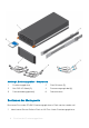
Abbildung 1. Erweiterungsgehäuse – Komponenten 1 Erweiterungsgehäuse 2 Rack-Schienen (2) 3 Mini-SAS-HD-Kabel (2) 4 Stromversorgungskabel (4) 5 Frontverkleidung (optional) 6 Dokumentation Bestimmen des Montageorts Bestimmen Sie, wo das SCv360-Erweiterungsgehäuse im Rack montiert werden soll. 1 Identifizieren Sie eine Stelle im Rack mit 4U Platz für das Erweiterungsgehäuse.
WARNUNG: Wenn Sie vorhaben, das Erweiterungsgehäuse über den unteren 20U eines Racks zu installieren, ist eine mechanische Hebevorrichtung zu verwenden, um Verletzungen zu verhindern. 2 Wenn Sie planen, das 1U-Kabelverwaltungsfach unterhalb des Erweiterungsgehäuse zu installieren, identifizieren Sie eine Stelle im Rack mit 5U Platz für das Erweiterungsgehäuse und das Kabelverwaltungsfach. Abbildung 2.
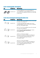
Tabelle 1.
Tabelle 3. Erweiterungsgehäuse Gehäusegriff-Set Teil Teilenummer Beschreibung 036-034-003 Erweiterungsgehäuse-Chassisgriff (Menge: 4) Zum Anheben des Erweiterungsgehäuse-Chassis auf eine mechanische Hebevorrichtung und zur Montage in einem Rack Tabelle 4.
Tabelle 5.
4 Befestigen Sie die Schienen, indem Sie 8-32 x 0,75 Zoll Schrauben (036-034-012) in die Löcher an der Vorder- und Rückseite der Schienen anbringen. Abbildung 3. Befestigen der Schienen am Rack 5 Richten Sie das U1-Kabelverwaltungsfach (042-033-060) so aus, dass der Pfeil nach oben in die richtige Richtung weist und sich die Seite des Fachs mit der Kennzeichnung FRONT an der Vorderseite des Racks befindet.
Abbildung 4. Ausrichten des Kabelverwaltungsfachs 6 Schieben Sie das U1-Kabelverwaltungsfach in die Schienen, bis es einrastet. Montieren des Erweiterungsgehäuse Installieren Sie die Schienen im Rack und montieren Sie das SCv360-Erweiterungsgehäuse auf den Schienen.
c d Drücken Sie die Schiene nach hinten, um die Schiene an der Rack-Stütze zu sichern. Ein hörbares Klicken zeigt an, dass die Schiene in der Stütze eingerastet ist. Stellen Sie sicher, dass die Stützen-/Öffnungsmechanik gesichert und an der Rack-Stütze angebracht ist. Abbildung 5. Bringen Sie die Schiene an der Rückseite des Racks an. 3 Bringen Sie die rechte Schiene an der Vorderseite des Racks an. a b Richten Sie die rechte Schiene mit den unteren zwei U-Einheiten des 4UMontageorts aus.
Abbildung 6. Bringen Sie die Schiene an der Vorderseite des Racks an. 4 Befestigen Sie die Schiene, indem Sie eine M5 x 10 mm Schraube (106-002-452) im größeren der beiden Löcher an der Vorderseite der Schiene montieren. 5 Befestigen Sie die Schiene, indem Sie eine M5 x 16 mm Schraube (106-002-453) im größeren der beiden Löcher auf der Rückseite der Schiene montieren. 6 Wiederholen Sie die Schritte 2 bis 5, um die linke Schiene zu installieren.
Abbildung 7. Ausfahren der Rack-Schienen d e f Schieben Sie die Rack-Schienen über die Schienen des ErweiterungsgehäuseChassis. Entfernen Sie die vier Griffe von den Seiten des Erweiterungsgehäuse-Chassis. Schieben Sie das Erweiterungsgehäuse-Chassis in das Rack.
Abbildung 8. Montage des Erweiterungsgehäuse im Rack 8 Wenn die Laufwerke, Kühlungslüfter, PSUs und EMMs aus dem Erweiterungsgehäuse entfernt wurden, bauen Sie die Komponente erneut im Gehäuse ein. 9 Sichern Sie das Erweiterungsgehäuse-Chassis und die obere Abdeckung. a b c d e 16 Montieren Sie die sechs Klemmmuttern (106-569-307) in den Löchern am Rack, die zu den Ansatzschrauben auf der Vorderseite des ErweiterungsgehäuseChassis ausgerichtet sind.
Frontverkleidung anbringen Wenn die Frontblende im Lieferumfang des SCv360-Erweiterungsgehäuse enthalten ist, montieren Sie die Blende an der Vorderseite des Erweiterungsgehäuse. 1 Richten Sie die Blende an der Vorderseite des Erweiterungsgehäuse aus. 2 Drücken Sie auf die zwei Riegel an der Vorderseite der Blende. Abbildung 9. Installieren der Blende 3 Drücken Sie die Blende in die richtige Position, bis sie am Erweiterungsgehäuse angebracht ist.
NOM-Informationen (nur Mexiko) Die folgenden Informationen beziehen sich auf die in diesem Dokument beschriebenen Geräte und entsprechen der mexikanischen Norm NOM: Importeur Dell México, S.A. de C.V. Javier Barros Sierra, No. 540, Piso 10, Col. Lomas de Santa Fe C.P.
Gehäuseverwaltungsmodule (EMMs) EMMs Zwei hot-swapfähige EMMs mit vier SAS-Ports /12 GB) pro EMM. Das Erweiterungsgehäuse unterstützt Mini-SAS-HD Kabel in den Längen 3, 4 und 5 Metern.
Umgebungsbedingungen Betrieb 20 % bis 80 % (nicht kondensierend) Bei Lagerung 10% bis 90% (nicht-kondensierend) Höhe über NN: Betrieb -16 bis 2300 m (-50 bis 7500 ft) Bei Lagerung -16 bis 10.600 m (-50 bis 35.