Dell PS Series Configuration Guide Abstract This configuration guide provides technical guidance for designing and implementing Dell™ PS Series storage solutions in iSCSI SAN environments.
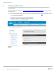
Revisions Revisions Date Description November 2019 vVols branding update May 2018 Minor updates December 2016 Minor updates January 2016 Small text updates and additions of PS4210, PS6210, and PS6610 array August 2014 Table 31: 14-drive RAID policy added May 2014 Minor updates for PS6210. Added information for LLDP February 2014 Section 9.7, Vertical port failover behavior in PS6210 controllers. New information in 8.1.2 on how to ensure a secure network environment.
Table of contents Table of contents 1 2 Purpose ........................................................................................................................................................................6 1.1 Dell EMC statement of support ...........................................................................................................................6 1.2 General statement ...........................................................................................................
Table of contents 8.2.3 Comparing inter-switch connection types .........................................................................................................41 9 Building a high-availability SAN ..................................................................................................................................43 9.1 Multi-path I/O ....................................................................................................................................................
Abstract Abstract This configuration guide provides technical guidance for designing and implementing Dell™ PS Series storage solutions in iSCSI SAN environments.
Purpose 1 Purpose The goal of this guide is to provide a single reference for technical information, links to other product and technical information, and recommended PS Series SAN design methodologies. This document is for informational purposes only and is offered as is. This document is not intended to be used as: • • 1.
Policies and limitations 2 Policies and limitations • • • • • 2.
Related publications 3 Related publications The following locations provide additional background and technical details supporting configuration of PS Series SANs. PS Series product documentation at https://eqlsupport.dell.com/support/download.aspx requires a support account to log in. To access the administration guides and other product documentation, follow this link and follow these steps: 1. Select PS Series Firmware. 2. Select the current version for the Download Page link. 3.
Related publications 3 4 PS Series Firmware download and support documents • • • • • • • • • • • 9 Dell EMC Storage Compatibility Matrix, including recommended switches and supported iSCSI initiators PS Series technical documents and videos Rapid EqualLogic Configuration Portal Switch Configuration Guides PS Series Hardware Documentation (requires support login) Dell EqualLogic Group Manager Administrator’s Manual (requires support login) VMware ESXi NIC Optimization and Best Practices with EqualLogic
PS Series storage arrays 4 PS Series storage arrays PS Series storage SANs provide a peer storage architecture comprised of one or more independent arrays. Each array contains its own controllers, cache, storage, and interface ports. Grouped together, they can create one or more single instance storage pools that are based on the IETF iSCSI standard.
PS Series storage arrays Starting with the introduction of the PS4100 and PS6100 family of arrays, configurations using 2.5” and 3.5” disks are available. PS4100/PS6100/PS6210 array models 11 Array model Drive type Number of drives PS4100E 3.5” SAS 7.2K RPM 12 PS4100X 2.5” SAS 10K RPM 24 PS4100XV 2.5” SAS 15K RPM 24 PS4100XV 3.5” SAS 15K RPM 12 PS6100E 3.5” SAS 7.2K RPM 24 PS6100X 2.5” SAS 10K RPM 24 PS6100XV 2.5” SAS 15K RPM 24 PS6100XV 3.
PS Series storage arrays PS4210, PS6210, and PS6610 array models 4.2 Array model Drive type Number of drives PS4210E 3.5” 7.2K NL-SAS 12 PS4210X 2.5” 10K SAS 24 PS4210XV 2.5” 15K SAS 24 PS4210XS 2.5” SSDs + 2.5” 10K SAS 24 PS6210E 3.5” 7.2K NL-SAS 24 PS6210X 2.5” 10K SAS 24 PS6210XV 2.5” 15K SAS 24 PS6210S 2.5” SSDs 24 PS6210XS 2.5” SSDs + 2.5” 10K SAS 24 PS6610E 3.5” 7.2K NL-SAS 42 x 2TB, 4TB, 6TB, or 8TB; or 84 x 4TB, 6TB, or 8TB PS6610X 2.
PS Series storage arrays PS4000, PS4100, PS4110, PS4210, and PS-M4110 groups only(a) All other groups(b) 512 per pool 1024 per pool 1024 per group with 2 pools 4096 per group with 4 pools Replication partners per group 16 16 Replication partners per volume 1 1 Members per group 2 16 (a) Configuration Persistent Reservation registrants per volume 8 if using vVols 13 Members per pool 2 8 Pools per group 2 4 Volumes per collection 8 8 Collections per group (snapshot and replication)
PS Series storage arrays Configuration PS4000, PS4100, PS4110, PS4210, and PS-M4110 groups only(a) All other groups(b) Associations 4096 4096 SCSI Power Fencing(l)(m) Up to 16 nodes Up to 16 nodes IPsec policies 256 256 IPsec security parameters 256 256 IPsec certificates(m) 10 10 a. A group can contain a maximum of two PS4000, PS4100, PS4110, PS4210, and/or PS-M4110 arrays. b.
PS Series storage arrays 4.3 Controller types in all models prior to PS4100/PS6100 Array controllers can be identified and differentiated by the controller "type" designation. Each controller type will have a different colored label to help quickly identify the controller type. Table 5 lists each Dell PS Series controller along with some characteristics about each.
PS Series storage arrays Controller type Faceplate Type 10 4.4 Network interfaces Storage type Notes 2 x 10GB SFP+ SAS 10Gb Ethernet 1 x 10/100Mb mgmt. SATA PS6010 – PS6510 SSD 2GB cache Controller types in PS4100/PS6100 and later models The new controller types available in the PS4100/PS6100 and later model arrays became available starting in August 2011. Table 6 lists each Dell PS Series controller along with some characteristics.
PS Series storage arrays Controller type Faceplate Type 15 Type 17 Network interfaces Storage type 2 x 10GbE SFP+ SAS 2 x 10GbaseT NL-SAS 10/100Mb mgmt.. SSD 1 x 10GbE SFP+ SAS PS4110 only 1 x 10GbaseT 1 x 10/100Mb mgmt. NL-SAS 4GB cache Notes 16GB memory per controller, 10GBaseT ports –can autonegotiate to 1G. Cache to Flash (C2F) destaging. New battery backup for cache. Hot swappable, Active-hot stand-by redundancy.
PS Series storage arrays 4.5 Array model PS-M4110 4.5.1 Controller type in PS-M4110 model The PS-M4110 controller is designed based on a modified version of the PS4100 controller. Host and SAS cards are combined to form a single unit fixed I/O module, connecting to the M1000e chassis infrastructure. Controller Storage blade type image Type 13 Network interfaces Storage type Notes 2 x 10Gb ports, (one per controller), connected through the backplane SAS NL-SAS Dual, hot-pluggable 10GbE controllers.
PS Series storage arrays S A N S A N LAN LAN SAN Stack SAN Stack LAN/Client Network LAN-to-Agg Uplinks Basic PS-M4110 configuration for data center-in-a-box 4.5.3 Networking considerations and guidelines Supported M-Series I/O modules: • • 10G KR is the only supported I/O Module (IOM). Switches: The list of supported switches can be found in the Dell EMC Storage Compatibility Matrix. The following are basic networking recommendations for implementing the PS-M4110 storage blade.
Controller firmware 5 Controller firmware 5.1 About member firmware Each control module in a group member must be running the same version of the PS Series Firmware. Firmware is stored on a compact flash card or a microSD card on each control module. Dell EMC recommends the following: • • • • • • • Always run the latest firmware to take advantage of new features and fixes. All group members must run the same firmware version.
Controller firmware 5.2 Firmware upgrade considerations Before beginning a firmware upgrade process, review the following documentation. These documents are available from the Dell PS Series Support site at https://eqlsupport.dell.com/support/download.aspx?id=6442456455 (Support ID required for login access).
RAID policies 6 RAID policies Each array in a PS Series array group is configured with a single RAID policy. Arrays (or group members) within the same storage pool that have the same RAID policy cooperatively work to host volumes by distributing those volumes over multiple arrays. Two things that are defined by the RAID policy are: • • RAID level Hot-spare configuration Each array implements a default RAID policy that includes a hot-spare.
PS Series capacity 7 PS Series capacity 7.1 RAID 6 drive layouts and total reported usable storage RAID 6 (striped set with dual distributed parity) combines N disks in an arrangement where each stripe consists of N-2 disks capacity for data blocks and two disks capacity for parity blocks. Each parity block generates parity using a different view of the data blocks depending on the RAID 6 implementation. RAID 6 can tolerate up to two drive failures per RAID stripe set at the same time without data loss.
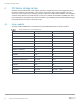
PS Series capacity Total reported usable storage when using hot spares: All models prior to PS4100/PS6100 Drive qty.
PS Series capacity Total reported usable storage when using hot spares: PS4210 Drive qty. 300 400 600 900 1200 2000 2400 3000 4000 6000 7 (SSD) - 1846(d) - - - - - - - - 17 (SAS) - - 7753(d) - - - - - - - 12 - - - - - 17012(a) - 24 5261(b) - 10522 15783(c) 21044(c) - a. b. c. d.
PS Series capacity 7.2 RAID 10 drive layouts and total reported usable storage Using a RAID 10 policy, Table 13 shows the drive layouts that are enforced based on the number of drives in each array/hot spare configuration, and the total usable storage available for each model. RAID 10 (mirrored sets in a striped set) combines two high performance RAID types: RAID 0 and RAID 1. A RAID 10 is created by first building a series of two disk RAID 1 mirrored sets, and then distributing data over those mirrors.
PS Series capacity Total reported usable storage when using hot spares: PS41x0/PS61x0 Disk qty. 146 200(e) 300 400(e) 500 600 6 - - - - 1064 - 12 650 920 14 781 - 24 1433 2027 a. b. c. d. e.
PS Series capacity 7.3 RAID 50 drive layouts and total reported usable storage Table 19 shows the drive layouts that are enforced when using a RAID 50 policy based on the number of drives in each array/hot spare configuration and the total usable storage available for each model. RAID 50 (RAID 5 sets in a striped set) is created by first creating two or more RAID 5 sets and then striping data over those RAID 5 sets. RAID 50 implementations can tolerate a single drive failure per RAID 5 set.
PS Series capacity Total reported usable storage when using hot spares: PS41x0/PS61x0 Drive qty. 146 300 400(e) 500 600 900 1000 1800 2000 2400 3000 6 - - - 1781 2129 - 3563 - 7280 - 11008 12 1044 2129 2949 3563 4280 6430 7137 - 14571 - 21975 14 1304 2670 - 4459 5353 8036 8930 16072 - 21429 - 24 2355 4815 6666 8038 9646 14474 16087 - 32727 - a. b. c. d. e.
PS Series capacity Total reported usable storage when using hot spares: PS6610 Drive qty. 600 800 900 1200 2000 3000 4000 6000 8000 42 - - 28243(b) 37658(b) 62764(a) - 128540(a) 192811(a) 257081(a) 84 38766(b) - 58149(b) 77532(b) - - 264642(a) 396963(a) 529284(a) a. 6610E only b. 6610X only Note: RAID 50 is not available through the Group Manager UI on PS6610 arrays. 7.
PS Series capacity Total reported usable storage when using hot spares: All models prior to PS4100/PS6100 Drive qty. 50(a) 100(a) 74 146 250 300 400 450 500 600 750 1000 2000 3000 7(b) - - - - 1111 - - - - - - - - - 8(c) - - - - 1333 - - - - - - - - - 14(d) - - 792 - 2671 - 4281 - 5354 - - - - - 1244 - 1827 3118 3744 4995 5622 6247 7500 9378 12508 25456 38461 - - - - - 38916 74580 115394 16 621 48 - a. b. c. d. e.
PS Series capacity 7.5 Array RAID configurations and associated RAID sets The tables show a logical drive layout when an array is initialized for the first time. The actual physical layout of drives can change and evolve due to maintenance and administrative actions. Spare drives can move as they are utilized to replace failed drives and newly added drives become the spares. It is not possible to determine which physical drives are associated with each RAID set.
PS Series capacity PS Series array RAID set relationship for each RAID type in a 14-drive configuration RAID policy Spare disk RAID set relationship Best practice RAID 6 (11+2) Yes 1 spare disk (6+2 HDD, 3+2 SSD)* RAID 10 2 spare disks (6+6) Yes RAID 50 2 spare disks (5+1, 5+1) For selected configuration RAID 5 1 spare disk (12+1) Not for business-critical data *Applies to the PS-M4110XS hybrid array configuration.
PS Series SAN design 8 PS Series SAN design A PS Series iSCSI SAN can be operated in any network that supports the industry standards and IP subnet design guidelines described in this section. Because of this flexibility, there are many network design and configuration choices that can affect SAN performance. The following sections provide details related to network design and configuration to support the use of a PS Series SAN.
PS Series SAN design 8.1.2 General requirements and recommendations For PS Series arrays, the following general SAN design recommendations apply: • To ensure a secure network environment, Dell EMC strongly recommends the following: - - • The network environment in which the group resides should be secure from network attacks such as packet sniffing or connection hijacking. This includes network hardware such as switches and routers.
PS Series SAN design - • • • • • • • • • • • • 8.1.3 FS7610 NAS Appliance: 8x10GbE Ethernet ports per appliance = 4 x 10GbE SFP+ Ethernet ports per NAS controller for client connectivity and 4 x 10GbE SFP+ Ethernet ports per NAS controller for SAN connectivity At least two iSCSI SAN ports per host (block level iSCSI access) are required for fully redundant SAN connectivity. Host ports can be 1GbE or 10GbE and the host speed should match the array port speed.
PS Series SAN design Dell EMC recommends against using QoS on the SAN switches for initiator-target communications paths. 8.2 Ethernet switches and infrastructure Any switch used in a PS Series SAN should meet the requirements listed in this section. Note: For a complete list of tested and validated components see the Dell EMC Storage Compatibility Matrix. Also review the included support policy statement.
PS Series SAN design • • • Support for unicast storm control: iSCSI in general, and PS Series SANs in particular can send packets in a very “bursty” profile that many switches could misdiagnose as a virally induced packet storm. Since the SAN should be isolated from general Ethernet traffic, the possibility of actual viral packet storms occurring is non-existent. In a PS Series SAN, the switches must always pass Ethernet packets regardless of traffic patterns.
PS Series SAN design 8.2.1.1 Stacking switches Stacking switches provides a simple method for creating a switch interconnection within a Layer 2 network infrastructure. Stacking is typically accomplished using a vendor proprietary, high-bandwidth, low-latency interconnect that allows two or more switches to be connected in such a way that each switch becomes part of a larger, virtual switch.
PS Series SAN design 8.2.1.3 Using a LAG to Connect Stacked Switches In some situations it may become necessary to expand the PS Series SAN by using more than one single switch stack. For example, you can link multiple stacks by creating a multi-link LACP based LAG between the switch stacks. A simplified stack plus LAG switch configuration is illustrated in Figure 5.
PS Series SAN design Connection speeds Interconnection guidelines 1-5 arrays: 10Gb of bandwidth per active array controller port (up to the aggregated maximum bandwidth of the IST). 6+ arrays: Use 1-5 array rule, then add 10Gb of additional bandwidth for each array added 8.2.3 Comparing inter-switch connection types Table 36 provides details and recommendations for selecting interconnect options.
PS Series SAN design Interconnect type LAG Primary purpose Analysis Create a data path between switches in one location or subnet with those in another location or subnet Advantages: • Leverages Ethernet standard extensions • Can be used to interconnect switches from different vendors • Can use Link Aggregation Protocols (LACP/EtherChannel) to pool multiple 1GbE or 10GbE links into a single logical link providing bandwidth and redundancy • Can upgrade switch firmware on each switch independently Concer
Building a high-availability SAN 9 Building a high-availability SAN Designing a redundant SAN requires the availability of redundant NICs or HBAs on each server. A redundant NIC configuration on the server requires at least two NICs. The information provided here does not address all of the possible variations in a SAN.
Building a high-availability SAN 9.1.1 PS Series MPIO requirements The following host port requirements must be met to use MPIO with PS Series SANs: • • • • • 9.1.2 At least two Ethernet ports are required on each host. While not required, it is preferable that these ports be on different physical adapters to ensure a highly available SAN solution. The host operating system must have a supported MPIO driver or service available. The ports used for MPIO cannot be “teamed” to other ports.
Building a high-availability SAN Redundant SAN Connection Paths: PS4100 Redundant SAN Connection Paths: PS4110/PS6110 9.3 Controller redundancy in all models Each array can be configured with either a single controller, or dual redundant controllers. The single controller configuration will provide the same level of I/O performance as a dual controller configuration. The dual controller configuration provides for redundancy. Dual controllers provide redundancy in the case of a controller failure.
Building a high-availability SAN 9.4 Basic controller failover behavior in all models To support redundant controller fail over, each Ethernet port on the active controller that is connected to the SAN must have its corresponding port on the passive controller also connected to the same SAN network. In the event of a controller failure, the passive controller will immediately activate and continue to process all data requests to the array. The following changes occur during fail over: • • 9.4.
Building a high-availability SAN Note how IP addresses are reassigned to their corresponding ports during the failover processes shown in Figure 9 and Figure 10. Fully connected controller failover 9.4.2 Controller failover behavior for: PS42x0/PS41x0/PS62x0/PS61x0/PS6610 In the event of a controller failure the following changes occur: • • The passive controller immediately activates and continues to process all data requests to the array.
Building a high-availability SAN Note: To prevent a switch failure from also disabling all paths between a host and its connected volumes, you should make sure that ports from each controller are connected to at least two different switches. You should also split vertical port pair connections between two switches to ensure 100% bandwidth capability is maintained in the event of a vertical port failover event. Both of these guidelines are illustrated in Figure 11.
Building a high-availability SAN Vertical port failover is bi-directional. If CM1 is the active controller then vertical port failover will occur from CM1 ports to CM0 ports if necessary. PS4100 vertical port failover PS6100 vertical port failover With PS4100/PS6100 family controllers, vertical port failover can ensure continuous full bandwidth is available from the array even if you have a link or switch failure.
Building a high-availability SAN PS4100 vertical port failover and optimal connection paths IMPORTANT: By alternating switch connection paths between ports in a vertical port pair, port failover allows the array to maintain 100% bandwidth capability in the event of a switch failure.
Building a high-availability SAN PS6100 vertical port failover process and optimal connection paths 9.6 Vertical port failover behavior in PS4110/PS6110 controllers In PS Series controllers prior to PS4110/PS6110 families, a link failure or a switch failure was not recognized as a failure mode by the controller. This caused a failure of a link or an entire switch to reduce bandwidth available from the array. Referring to Figure 12 or Figure 13, assume that CM0 is the active controller.
Building a high-availability SAN 4110/6110 vertical port failover With the PS4110/PS6110 family of controllers, vertical port failover can ensure continuous full bandwidth is available from the array even if you have a link or switch failure. This is accomplished by combining 10GbE “eth0” ports in each controller into a single logical port from the point of view of the active controller. In a fully redundant SAN configuration, you must configure the connection as shown in Figure 17.
Building a high-availability SAN 4110/6110 Vertical port failover scenario 53 Dell PS Series Configuration Guide
Building a high-availability SAN 9.7 Vertical port failover behavior in PS4210/PS6210/PS6610 controllers In PS Series controllers prior to PS4110/6110/6210 families, a link failure or a switch failure was not recognized as a failure mode by the controller. This caused a failure of a link or an entire switch to reduce bandwidth available from the array. Referring to Figure 13, assume that CM0 is the active controller.
Building a high-availability SAN PS6210 Vertical port failover scenario 55 Dell PS Series Configuration Guide
Mixed-speed environments: Integrating 1GbE and 10GbE SANs 10 Mixed-speed environments: Integrating 1GbE and 10GbE SANs With the introduction of 10GbE, some situations that require 1Gb arrays and 10Gb arrays coexisting in the same SAN infrastructure. PS Series arrays support operation of 1Gb and 10Gb arrays within the same group.
Blade server chassis integration 11 Blade server chassis integration Integrating the PowerEdge M1000e Blade Server Solution (or any third-party blade chassis implementation) requires additional SAN design considerations. Each M1000e can support up to three separate networking “fabrics” that interconnect ports on each blade server to a pair of blade I/O modules within each chassis fabric through an intervening chassis midplane interface.
Blade server chassis integration 11.1 Designing a SAN using blade chassis I/O modules with arrays There are three categories of SAN designs for M1000e blade chassis integration: • • • Blade IOM switch only (Direct-Attached): Network ports of both the hosts and storage are connected to the M1000e blade IOM switches. No Top of Rack (ToR) switches are required. The switch interconnect can be a stack or a LAG, and no uplink is required.
FS Series NAS configuration 12 FS Series NAS configuration This section provides detailed connection diagrams demonstrating how to set up fully connected iSCSI SAN and client LAN connection paths for the FS7500 and FS7600/FS7610 appliances. Note: It is recommended to keep the client and SAN side networks physically separate and deploy at least two switches on both sides to provide redundancy in the event of a switch failure. Table 38 lists the basic functional details for each FS Series product.
FS Series NAS configuration 12.1 FS7500 connection paths The FS7500 appliance is comprised of two peer system controller nodes. In the required fully cabled configuration, each controller node needs thirteen separate Ethernet cable connections. Thus, a single FS7500 appliance comprised of two controller nodes requires a total of 26 Ethernet connections (four connecting to the client LAN switches and nine connecting to the iSCSI SAN fabric switches.) Figure 21 shows the client LAN connection paths.
FS Series NAS configuration Note: With the exception of the IPMI connection paths, corresponding ports on each controller node must connect to the same SAN switch. This connection pattern is shown in Figure 22. Connection Paths for FS7500 iSCSI SAN, IPMI and Controller Interconnect The inter-switch connection sizing guidelines provided in section 8.2.2 also apply to FS7500 SAN design. The FS7500 mirrors the write cache between controller nodes.
FS Series NAS configuration 12.2 FS7600/FS7610 connection paths The PS Series NAS appliances require the following networks: • • Client network: Used for client access to the NFS exports and CIFS shares hosted by the NAS cluster. SAN/internal network: Used for internal communication between the controllers and communication between the controllers and the PS Series SAN. The SAN and Internal networks use the same set of switches.
FS Series NAS configuration FS7600 network FS7610 network 63 Dell PS Series Configuration Guide
FS Series NAS configuration Installation/expansion • • If installing FS7500/FS76x0 into an existing PS Series SAN, verify the existing LAN and SAN networks meet the minimum requirements. All NAS appliances in a NAS cluster must be of the same speed. Appliances with different connectivity cannot be mixed in a NAS cluster. - • An FS7500 cluster can be expanded by using another FS7500 or an FS7600 but not an FS7610. Do not block IPv6 traffic on the SAN internal switches when utilizing FS Appliances.
Data Center Bridging (DCB) 13 Data Center Bridging (DCB) The enhancement to the Ethernet Specifications (IEEE 802.3 specifications) called Data Center Bridging (DCB) enables bandwidth allocation and lossless behavior for storage traffic when the same physical network infrastructure is shared between storage and other traffic. The network is the fundamental resource that connects the assorted devices together to form the datacenter Ethernet infrastructure.
Data Center Bridging (DCB) 13.1 DCB overview DCB is a collection of Standards designed to improve networking and management in the data center that enables iSCSI SANs or FCoE SANs or both to converge with regular server LAN traffic on the same physical infrastructure. DCB aims to increase operational efficiency, constrain costs, and ease network management.
Data Center Bridging (DCB) Designing a converged network deployment with components that have no DCB support or partial DCB support is not recommended for end-to-end converged I/O. Configurations with components that have no DCB support or partial DCB support may result in loss of expected functionality or may be functional without meeting the converged network objectives. Note: It is not recommended to share network infrastructure with DCB and non-DCB components.
Network ports and protocols A Network ports and protocols PS Series groups use a number of TCP and UDP protocols for group management, I/O operations, and internal communication. If you have switches or routers set to block these protocols, you may need to unblock them to allow management or I/O operations to work correctly. The required and optional protocols are listed in the following sections. A.
Network ports and protocols Type Port Protocol Access UDP 161 SNMP To and from group IP address 514 Syslog From group IP address Syslog UDP PS Series Diagnostics TCP 21 FTP Software update and diagnostic procedures; to all individual member IP addresses TCP 25 SMTP E-mail and diagnostic notifications; from all individual member IP addresses to the configured SMTP server 123 NTP To external Network Time Protocol (NTP) sources for time-of-day clock synchronization NTP UDP 69 Dell PS
Upgrade paths for PS Series arrays B Upgrade paths for PS Series arrays PS Series upgrade paths 70 Currently shipping arrays Latest available conversion model 1Gb to 10Gb conversion availability Drive upgrades availability (to half populated arrays) PS6610 None N/A Yes PS4210 None N/A Yes PS6210 None N/A Yes PS-M4110 None N/A Yes End of sales life arrays Latest available conversion model 1Gb to 10Gb conversion availability Drive upgrades availability (to half populated arrays) PS