
White Papers

BP1031 SAN Design Best Practices for M1000e Blade Servers and EqualLogic PS Series Storage (1GbE) 31
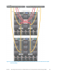
percentage the loss of bandwidth is not a factor. Of all multiple switch tier designs, the uplink stack
(highlighted in green) retains by far the most uplink bandwidth.
All applicable SAN designs retain enough ISL bandwidth to accommodate the expected ISL traffic of
the remaining host ports. As discussed in Section 5.2.2 this is normally about 50% of the expected
throughput between the host and storage ports.
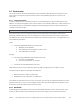
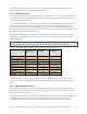
Green cells indicate the recommended SAN design within each design category based on all factors
considered during testing, while orange cells indicate designs that might not be preferred.
Table 7 A comparison of the way each SAN designs tolerates a blade IOM switch failure
Reduction in
connected host
ports
Reduction in uplink
bandwidth
Reduction in ISL
bandwidth
Blade IOM only with ISL
stack 32 16 N/A 32Gbps N/A**
Blade IOM only with ISL
LAG 32 16 N/A 20Gbps N/A**
TOR only with ISL LAG
N/A
N/A
N/A
Blade IOM and TOR with
four-way stack
32 16
32 16Gbps
32 16Gbps
Blade IOM and TOR with
three-way LAG 32 16 40 20Gbps 20 20Gbps
Blade IOM and TOR with
uplink stacks
32 16
64 32Gbps
40 20Gbps
Blade IOM and TOR with
ISL stacks
32 16
40 20Gbps
64 32Gbps
**ISL bandwidth is no longer relevant because the switch failure eliminates the ISL. Note that this
happens in conjunction with the loss of the 50% of the host ports connected to the failing blade IOM
switch.
5.3.3 Recommendations
In both the TOR and blade IOM switch failure scenarios, the blade IOM switch and TOR switch with
uplink stacks SAN design retained as many or more host port connections while retaining the highest
amount of uplink bandwidth of any other applicable SAN design.
5.4 Scalability
The final criterion by which SAN designs will be evaluated is scalability. Note that the scalability data
presented in this section is based primarily on available port count. Actual workload, host to array port
ratios, and other factors may affect performance. Section 5.4.1 will list the maximum number of array
members and the resulting host/storage port ratios for each SAN design. Section 5.4.2 will discuss
how each SAN design would accommodate additional M1000e blade chassis or PS Series array
members.
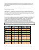
5.4.1 Host / array member port ratios for single chassis
The following table shows the maximum number of array members supported by each SAN design
assuming a single M1000e chassis and 16 half-height blade servers with two M6348 switches or two
pass-through IO modules, two SAN ports per host and, if applicable, two 48-port TOR switches. Note
that the blade IOM switch only SAN designs allow the fewest array members per blade chassis and
hence have the highest host/storage port ratio, 2:1. TOR switch only designs support twice as many